Skoči na glavni sadržaj

Prethodno priopćenje

https://doi.org/doi.org/10.32909/kg.22.39.1

Development of a Conceptual Model of a Road Accident Geoinformation System

Ivan Kunchev orcid id orcid.org/0000-0001-5313-5054 ; Odjel za geodeziju i geoinformatiku, Geodetski fakultet, Sveučilište za arhitekturu, građevinarstvo i geodeziju Sofija, Bugarska
Marija Angelova ; Odjel za geodeziju i geoinformatiku, Geodetski fakultet, Sveučilište za arhitekturu, građevinarstvo i geodeziju Sofija, Bugarska


Puni tekst: hrvatski pdf 4.355 Kb

str. 5-19

preuzimanja: 0

citiraj

Puni tekst: engleski pdf 4.355 Kb

str. 4-18

preuzimanja: 0

citiraj

Preuzmi JATS datoteku


Sažetak

The field of road accidents requires a specific geoinformation system to provide functionalities for creating and managing intelligent geographically-oriented spatial-temporal models for spatial analysis. The aim of this study is to present a conceptual model of a geoinformation system of road accidents, defined in accordance with the requirements of international standardization. The approach for international standardization and conceptual modeling of geoinformation, as well as the principles of object-oriented modeling, methods of abstraction and classification were used. As a result, a Use Case and a Class diagram, presented in the Unified Modeling Language, were developed. In conclusion, the standardized conceptual model is defined as an important initial stage in the creation of a geoinformation system of road accidents, which is related to the correct formalized description of the domain and the presentation of structural types of geoinformation processes, and subsequently can be automatically and in the unified manner transposed into a functional physical model for the analysis of road accidents.

Ključne riječi

international standardization; UML; spatial-temporal model; integrated transport approach

Hrčak ID:

300935

URI

https://hrcak.srce.hr/300935

Datum izdavanja:

28.4.2023.

Podaci na drugim jezicima: hrvatski

Posjeta: 304 *


References / Literatura


Al-Shabi M, Ansari G (2012) Modeling of Traffic Accident Reporting System through UML Using GIS. International Journal of Advanced Computer Science and Applications, 3, 6, 26-30.


Angelova M , author. (2020) Geoinformation System of Road Accidents, Master Thesis, University of Architecture, Civil Engineering and Geodesy, Sofia, Bulgaria.


Dimidenko A , author. (2020) Digital Road Model. Technologies of creation and application.


Dimidenko A, Korolev A, Kirichenko A (2021) Application of technologies of KB "Panorama" to build a unified geoinformation space of the region. Geoprofi, 2


Govorov M (2008) Standards, specifications and metadata for Geographic information. Vilnius, Lithuania


Hongmin S, Hongzhou P (2022) Architecture Design and Code Implementation of Road Network Path Search System. Wireless Communications and Mobile Computing, 2022. https://doi.org/DOI: 10.1155/2022/4235523


INSPIRE Thematic Working Group Transport Networks. (2014) D2.8.I.7 Data Specification on Transport Networks – Technical Guidelines.


Kresse W, Danko D (2012) Springer Handbook of Geographic Information. Springer,London


Kunchev I (2021) Standardization in the field of Geodesy and Cartography in Bulgaria - is it worth it?. In: 21st International Multidisciplinary Scientific GeoConference SGEM 2021, Albena, Bulgaria, 16 - 22 August, 419-425. https://doi.org/DOI: 10.5593/sgem2021/2.1/s09.52


Kunchev I (2022) Geodetic and geoinformation aspects in connection with the creation of a Geoinformation system for the territory of Bulgaria. In: 22nd International Scientific Multidisciplinary Conference on Earth and Planetary Sciences SGEM 2022, Albena, Bulgaria, 2 – 11 July (accepted scientific article for publication)


Lipiyska Y, Angelova M (2021) International Standardization in GIS – From the Abstract Model to the Application Level. Geodesy, Cartography and Land Management, 5-6, 18-22.


Piccinini F, Pierdicca R, Malinverni E (2020) A Relational Conceptual Model in GIS for the Management of Photovoltaic Systems. Energies, 13, 11, 2860-2882. https://doi.org/DOI: 10.3390/en13112860


Sanders B, Sanders W (2007) ActionScript 3.0 Programming: Overview, Getting Started, and Examples of New Concepts. Adobe Systems Incorporated,California


Seldi M, Scholz M, Huemer C, Kappel G (2015) UML Classroom – An introduction to object-oriented modeling. Springer International Publishing,Switzerland


This display is generated from NISO JATS XML with jats-html.xsl. The XSLT engine is libxslt.


1. Introduction

Geographic information systems (GIS) are a universal and multifunctional tool to sustainably manage the economically important field of transport and the inevitably related road accidents. This national and international problem requires the provision of functionalities for the creation and management of intelligent geographically-oriented spatial-temporal models for the analysis of road accidents and subsequently making economically important decisions, including taking preventive measures to reduce road injuries at the national and regional level.

In order to create a complete GIS that meets all the up-to-date geoinformation needs, one of the most complex and fundamental issues should be solved − its proper design through a correctly defined formalized description of the subject area, i.e. the formation of a conceptual model for discovering the internal and external relations between the objects in the system, as well as for presenting the typical information processes in it (Kunchev 2021,2022). The conceptual model is determined (Kresse, Danko 2012) as an abstract model independent of implementation with four levels of abstraction (meta-metamodel, metamodel, application level and data level), defining the concepts of a selected piece of the real world to be modeled, and describing completely and unambiguously the features from a given domain.

The topic of conceptual modeling of road network systems is discussed in the recent research (Hongmin, Hongzhou 2022), where a Unified Modeling Language (UML) class diagram is used in the process of designing a Road Network Path Search System. The diagram serves only for visual modeling and understanding the static structure of the system − the UML model is general and it is used for typification of processes through interfaces for the interaction of classes. The GIS conceptualization approach is also used (Piccinini et аl. 2020) in the creation of a conceptual model of a management system that serves to determine a relational database when implementing it in a GIS. The model is used for binding the tables in the database, i.e., it is primarily used as a database model. Modeling in the traffic accident domain with the aim of solving real time problems using UML is also considered in the important research (Al-Shabi, Ansari 2012) in the development of a Traffic Accident Reporting System. In the research GIS is а separate element, and for this reason its modeling is not considered. Instead, a relationship is determined between the system, including insurance companies and police officers, GIS, viewers and vehicles, and the incident reporting process is introduced.

The standardization and unification of the conceptual model is a topical issue from the point of view of the subsequent functionality of the system - starting with the general terminology for international understanding of geoinformation, through specification and visual modeling for better understanding of models and an automated transition to a platform-specific model, to the harmonization of heterogeneous data and the exchange of geoinformation and geodata services for achieving interoperability.

2. Use of International Standardization in Conceptual Modeling

The current approach to creating modern spatial-temporal models is based on a series of international standards and technical specifications − ISO 19 100 Geographic information. This family of standards (and in particular ISO 19 101 Reference Model) presents a methodology for moving from the real world to the conceptual model by introducing conceptual formalism for its description, based on the object-oriented paradigm (OOP). This methodology includes a formal description – conceptual schema presented by the object-oriented UML, which is profiled by ISO in the domain of geoinformation modeling to achieve interoperability. When the conceptual schema is required for a specific application, it`s called an application schema (Govorov 2008), part of which are the instances of classes - objects, found in terminology as feature instances. The selected UML modeling language allows the transition from the conceptual to application schema and subsequent automated coding in eXtensible Markup Language/Geography Markup Language (XML/GML), which in turn makes it possible to create an application model and data model for the physical implementation of a geoinformation system.

3. Development of a Conceptual Model of a Road Accident Geoinformation System

A fundamental element in the development of the conceptual model of a GIS of road accidents is the application of the approach proposed by ISO/TC 211 Geographic Information − Model Driven Architecture (MDA), described in (Govorov 2008) and practically presented in (Lipiyska, Angelova 2021).

After the initial verbal level of description of the subject area, scope and objectives of the system, the expected results, as well as the selected methods and approaches to be applied, and the subsequent verbal stage of general conceptualization are needed (Angelova 2020). The next step is detailing the tasks and moving from verbal form to the physical elaboration of the schema through specialized software. To create the conceptual model of a road accident GIS, the world's leading software for visual modeling and design was used, which allows the application of current international standards and technical specifications in the subject field − Enterprise Architect, version 16.0.

Two UML diagrams have been created, Use Case and Class, the main aspects of which will be discussed.

2.1. Use Case diagram

The structuring and description of processes in a complex GIS are an integral part of its management, operation and optimization. To perform this process, the standardized approach to conceptual modeling involves developing a Use Case diagram, which in essence aims at the conceptual presentation of the processes in the system − the participants in it (actors), the actions they perform, the elements and the relations between them. In general, the Use Case diagram answers three questions (Seldi et al. 2015) − what is described (the system), who participates in it or who manages it (the actors) and what the actors do (the so-called use cases).

The defined actors and their associated roles in the road accident GIS will be briefly described.

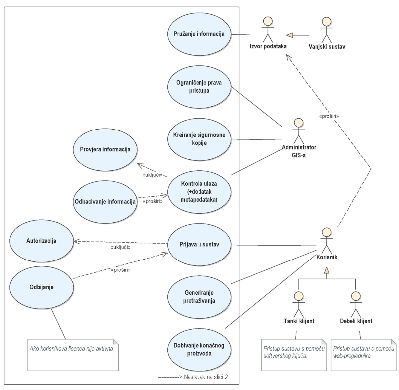
In the created Use Case diagram (Figure 1 andFigure 2) the spatial information comes from sources of information, which can be external systems (including systems involved in the regulation of the transport system, or the user of the system under certain conditions). The external systems are represented by a type of generalization relationship, which means inheritance to the actor, the source of information. The main idea of obtaining input information about a road accident can be divided into two aspects depending on the goals − collecting datasets for some period for the purpose of statistics and analysis and collecting information about a single road accident that occurred near real time. In the first case, the sources can be official agencies (in Bulgaria these are: Road Infrastructure Agency, State Road Safety Agency, Ministry of Interior). In the second case, from a conceptual point of view, data sources can be system users themselves (witnesses of the accident or law enforcement officers for example), as well as traffic police officers through video surveillance.

An important component such as the administration of access rights is affected. Who can access spatial datasets, products and services in different forms (for example, only viewing, editing, updating, accessing, etc.). This part is invariably related to the user's login to the system, using the two types of relationships that are possible between the cases − "include", in which the base case always requires the behavior of the included one, while the included one can be executed independently, and "extended", in which case the base can use the functionality of the “extended”, but is not required. For the second type of relations, a condition should be set to fulfill the additional case, as in the specific diagram which defines that there will be a rejection from the system if the user's license is not active. It should be noted that the actors do not represent a specific user, but a role that the user assumes (they are authorized to perform a use case associated with this role) (Seldi et al. 2015). The restriction of access rights, together with the creation of archival copies of the system and the provision of input control are activities associated with one component − GIS administrator. It should be noted that the actors may or may not be people (for example, a server or other application program), depending on the case.

Input data control is a topic that is extremely important for a quality geodata product, as data is one of the most expensive and time-consuming components in any GIS. Here it is linked to the metadata database defined by international standardization, in particular ISO 19 115 – Metadata. To objectively present the reality and correctly understand the information regarding the created conceptual models and used abstractions, documentation in the form of metadata should be created to allow the correct use of a resource. Also, from the point of view of facilitating the sharing and efficient use of geodata, in addition to the basic elements of metadata, it is important to provide a common basis for understanding geodata datasets, which can be done by applying the metadata standard and building sets of geodata metadata in accordance with it (Govorov 2008). ISO 19 115 defines the minimum quantity of metadata for each input dataset, mandatory and recommended components, etc. Moreover, the availability of the defined metadata set for each input dataset is a favorable prerequisite for all subsequent processes in the system − starting with data entry, ensuring their correct classification and structuring, ensuring topological connectivity, which is a key component of all spatial information services, the comprehensive processing of data in various forms and, of course, the correct exchange, meeting international standards and aiming at interoperability.

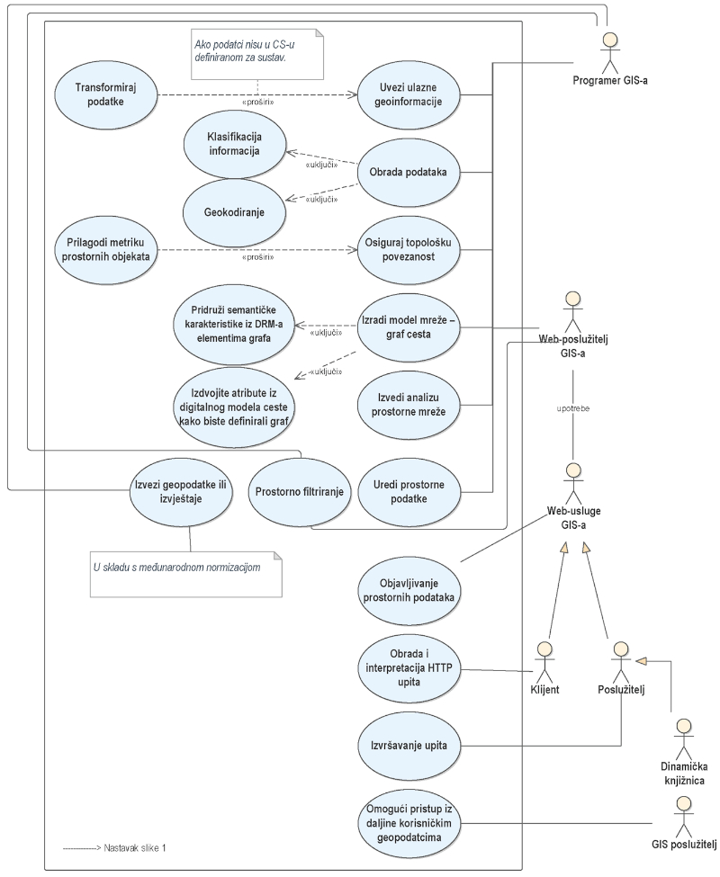
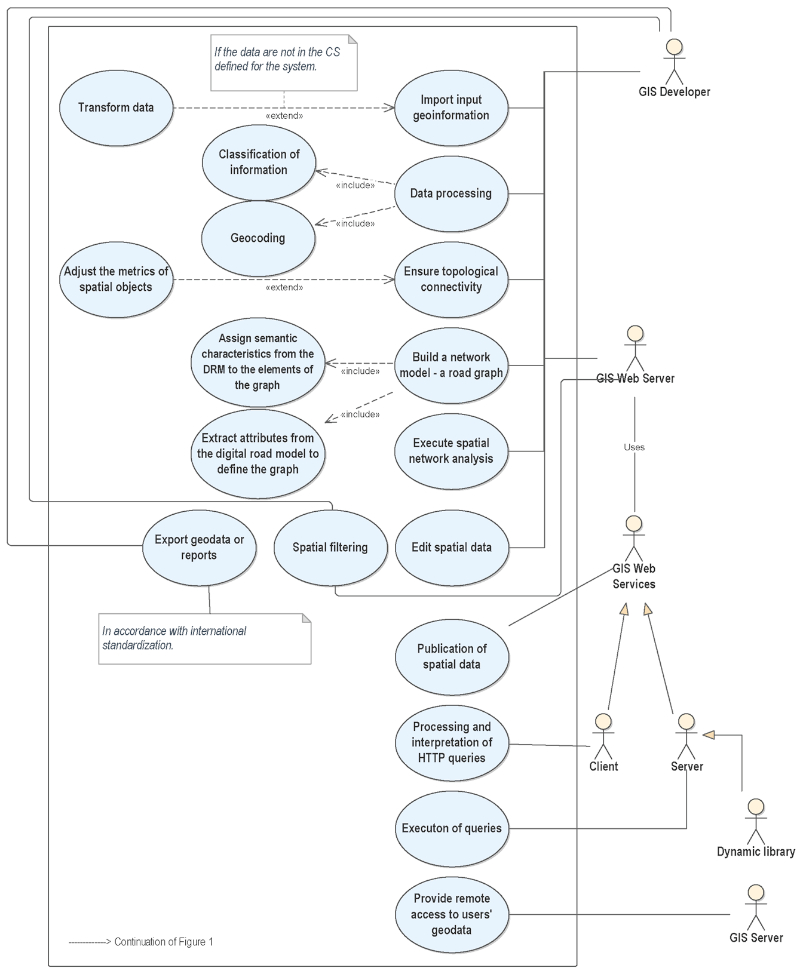
The system involves the division into two main major components – the desktop and server part. The specificity is that in both cases all the described functionalities for working with geodata are available. The difference is in the access of clients (which are differentiated into “thick” and “thin”), as well as in the software components involved in the processes of accessing and transferring information. On the server part, the final product reaches the customers through a web browser and includes the components − GIS Server, GIS Web Server and GIS Web Services. The responsibility of the GIS Server in the system is to provide system users with remote access to geodata or spatial databases, allowing the same data to be processed by any number of users who are connected to the server. The basic idea of this functionality is that the data is automatically updated for all users when making a change. The GIS Web Server is responsible for providing access to data based on GIS Web Services. It can also be considered an autonomous GIS, as it performs all its functionalities. GIS Web services, in turn, provide the connection between users and server applications. These are web services for publishing spatial data according to the protocols of the Open GIS Consortium (OGC) − Web Map Services (WMS), Web Map Tile Services (WMTS), Web Feature Services (WFS), Web Coverage Services (WCS) etc. The integration of these specifications is a key component as it provides unified access, search, processing, and exchange, creating opportunities for interaction between different systems. GIS Web Services has a client-server architecture, the client part of which is responsible for processing and interpreting HTTP requests, and the server − for processing client requests, analysis, and transmission for execution to dynamic libraries (Dimidenko et al. 2021).

The general functionality of the road accident GIS described in the Use Case diagram includes the development of a network digital road model by generating a road graph, the edges of which are given all available characteristics of road objects (number of lanes, different classifications, type of road pavement, etc.) (Dimidenko 2020). Another main activity is the use of some of these attributes to define the components of the road graph (for example, permitted speed, which can then be used in algorithmization for one of the main tasks with the graph − finding the shortest distance).

The diagram thus defined shows the user-system connections, data source-system connections, as well as the internal connections, indicating the typed information processes and differentiating the system into desktop and server.

Figure 1. Road Accident Use Case diagram Part 1
kig-22-4-g1.jpg

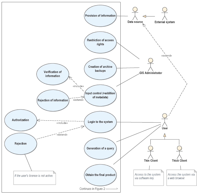
Figure 2. Road Accident Use Case diagram Part 2 (continuation ofFigure 1)
kig-22-4-g2.jpg

2.2. Class diagram

The applicability of the chosen objects by ISO modeling language, which achieves a complete and unambiguous definition of rules for structured description of a system − UML is objective since it is a language that supports OOP, allowing the creation of a real-world analogue. An essential property of OOP that is implemented through UML is that it can be used in the interaction of a complex program with users, elements, other programs and, of course, data (Sanders, Sanders 2007).

The created conceptual schema, presented by the class diagram, uses the OOP functionalities − inheritance-type relations are defined (one of the main and most important characteristics of OOP due to its function of reducing repeatability), aggregation and composition between different classes, and abstract classes are defined, the specificity of which is that they are not instantiated directly − only their subclasses are instantiated, which inherit the characteristics of their superclasses. It is important to note that all abstract classes are defined in italic font.

The starting point for creating the conceptual schema of a road accident GIS is the idea set out in (INSPIRE Thematic Working Group Transport Networks, 2014), which aims to achieve an integrated transport approach between different types of network transport infrastructures through the inherent ISO 19 100 extensible mechanism combined with single presentation of data and repeated usage.

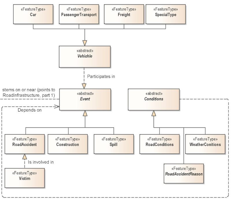
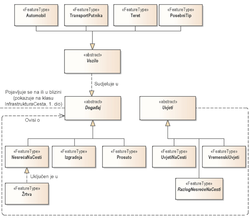
The overall model is differentiated into two submodels that are interconnected − road infrastructure and road accidents (Figure 3, (Figure 4).

For the road infrastructure feature classification, the normative regulation, valid for the territory of the Republic of Bulgaria and concerning the management, administration, construction, repair, maintenance and financing of the roads, as well as the management of the road infrastructure safety in the Republic of Bulgaria – Law of Roads in force since 11 August 2020 is used in combination with the accompanying regulations for its application and the current Ordinance for Large-scale topographic signs in scales 1:5000 and 1:10 000. In road accident classification in the classes, a causal relationship is defined by a detailed description of the causes and results of an event.

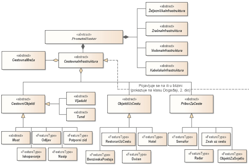
In general, the transport system consists of road, rail, air, water, and cable infrastructure. In turn, the road infrastructure consists of a road network, road facilities, road accessories and roadside facilities. The road network is presented as an abstract superclass of all types of roads − highways, national road network roads and others, where every different type of road is a separate class from which to instantiate objects in terms of future different visualization. The approach is similar for road facilities such as a bridge, tunnel, viaduct − a separate class is defined for different roads (for example, a motorway tunnel, a bridge on the road from the national road network, etc.). Due to figure size limitations, complete diagrams with all their components cannot be presented, so the main ones are described. Road accessories and roadside facilities are also defined as abstract classes in terms of the fact that the final collection of instances will be instantiated by their generalized subclasses − for example a specific traffic light, road sign or petrol station.

Road accidents are defined as a subclass with a relation of type generalization of a superclass Event. Repairs and spills are also classified as events occurring on or near the road infrastructure. Classes of vehicles and victims are defined, and they participate in the accidents class. A separate class of conditions is generated, the inheritor of which are road conditions and meteorological conditions. Successor to the class conditions are also reasons for/behind accidents.

Figure 3. Road Accident Elements of the Class diagram Part 1
kig-22-4-g3.jpg

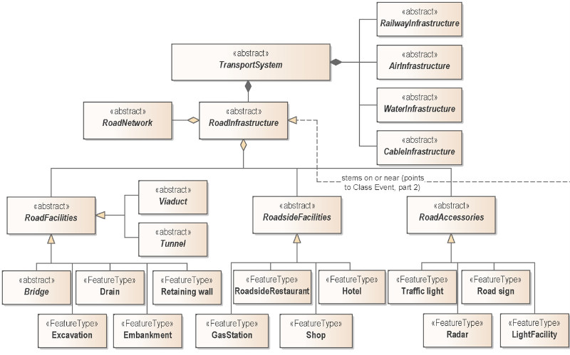
Figure 4. Road Accident Elements of the Class diagram Part 2 (continuation ofFigure 3)
kig-22-4-g4.jpg

4. Conclusion

Conclusions can be differentiated into two main aspects. The first is the justification of the need for standardized and unified modeling through a visual modeling and design tool such as UML − the correct formalized description of the subject area, typed processes in the system and features from the real world in the domain with the relations between them, determined by the required level of abstraction, i.e. the creation of a conceptual model is a prerequisite for correct and successful implementation, subsequent algorithmization and optimization of any/every GIS. The second aspect is the integration of international standardization in processes, geodata, products and services from the initial stage of GIS creation. The created conceptual model, for which a thorough multi-stage analysis of objects and relations between them in the transport system domain has been performed and various terminologies and existing structures have been studied, is built on the foundation of international standardization. This quality allows its use for future automated creation of an applied model and data model for the physical realization of a road accident GIS, offering common terminology to universally understand the geoinformation and achieve interoperability. Based on the thus defined foundation, tools for spatial analysis of road accidents can be built, which will serve to reduce road traffic injuries and will provide important functionalities for the Bulgarian transport system.


1. Uvod

Geografski informacijski sustavi (GIS) univerzalni su i višenamjenski alat za održivo upravljanje ekonomski važnim područjem prometa i neizbježno povezanim prometnim nesrećama. Taj nacionalni i međunarodni problem zahtijeva osiguranje funkcionalnosti za kreiranje i upravljanje inteligentnim geografski orijentiranim prostorno-vremenskim modelima za analizu prometnih nesreća i naknadno donošenje ekonomski važnih odluka, uključujući poduzimanje preventivnih mjera za smanjenje prometnih ozljeda na nacionalnoj i regionalnoj razini.

Za izradu cjelovitog GIS-a koji zadovoljava sve suvremene geoinformacijske potrebe potrebno je riješiti jedno od najsloženijih i temeljnih pitanja − njegovo pravilno projektiranje kroz pravilno definiran formalizirani opis predmetnog područja, odnosno formiranje konceptualnog modela za otkrivanje unutarnjih i vanjskih odnosa između objekata u sustavu, kao i za prikaz tipičnih informacijskih procesa u njemu (Kunchev 2021,2022). Konceptualni je model određen (Kresse, Danko 2012) kao apstraktni model neovisan o primjeni s četirima razinama apstrakcije (meta-metamodel, metamodel, razina aplikacije i razina podataka), definirajući koncepte odabranog dijela stvarnog svijeta koji će biti modelirani te potpuno i nedvosmisleno opisuju značajke iz zadane domene.

Tema konceptualnog modeliranja sustava cestovne mreže razmatrana je u nedavnom istraživanju (Hongmin, Hongzhou 2022), gdje se Unified Modeling Language (UML) dijagram klasa koristi u procesu projektiranja sustava za traženje putova cestovne mreže (Road Network Path Search System). Dijagram služi samo za vizualno modeliranje i razumijevanje statičke strukture sustava − UML model je opći i koristi se za tipizaciju procesa kroz sučelja za interakciju klasa. Pristup konceptualizacije s pomoću GIS-a također se koristi (Piccinini i dr. 2020) u kreiranju konceptualnog modela sustava upravljanja koji služi za određivanje relacijske baze podataka prilikom uključivanja u GIS. Model se koristi za povezivanje tablica u bazi podataka, odnosno prvenstveno se koristi kao model baze podataka. Modeliranje u području prometnih nesreća s ciljem rješavanja problema u stvarnom vremenu korištenjem UML-a također se razmatra u važnom istraživanju (Al-Shabi, Ansari 2012) u razvoju sustava za izvješćivanje o prometnim nesrećama (Traffic Accident Reporting System). U istraživanju je GIS zaseban element te se iz tog razloga ne razmatra njegovo modeliranje. Umjesto toga, utvrđuje se odnos između sustava uključujući osiguravajuće kuće i policijske službenike, GIS, gledatelje i vozila te se uvodi proces prijave incidenata.

Standardizacija i unifikacija konceptualnog modela je aktualno pitanje sa stajališta naknadne funkcionalnosti sustava − počevši od opće terminologije za međunarodno razumijevanje geoinformacija, preko specifikacije i vizualnog modeliranja za bolje razumijevanje modela i automatiziranog prijelaza modelu specifičnom za platformu, harmonizaciji heterogenih podataka i prijenosu geoinformacijskih i geopodatkovnih usluga za postizanje interoperabilnosti.

2. Upotreba međunarodne normizacije u konceptualnom modeliranju

Sadašnji se pristup izradi modernih prostorno-vremenskih modela temelji na nizu međunarodnih normi i tehničkih specifikacija − ISO 19 100 Geografske informacije. Ta obitelj normi (a posebno Referentni model ISO 19 101) predstavlja metodologiju za prelazak iz stvarnog svijeta u konceptualni model uvođenjem konceptualnog formalizma za njegov opis, temeljen na objektno orijentiranoj paradigmi (OOP). Ta metodologija sadrži formalni opis – konceptualnu shemu predstavljenu objektno orijentiranim UML-om, koji je ISO profilirao u području geoinformacijskog modeliranja kako bi se postigla interoperabilnost. Kada je konceptualna shema potrebna za određenu aplikaciju, naziva se aplikacijska shema (Govorov 2008), čiji su dio instance klasa − objekti koji se u terminologiji nalaze kao instance značajki. Odabrani jezik za modeliranje UML-a omogućuje prijelaz s konceptualne na aplikacijsku shemu i kasnije automatizirano kodiranje u jeziku eXtensible Markup Language/Geography Markup Language (XML/GML), što zauzvrat omogućuje stvaranje aplikacijskog modela i podatkovnog modela za fizičku primjenu geoinformacijskog sustava.

3. Izrada konceptualnog modela geoinformacijskog sustava prometnih nesreća

Temeljni element u razvoju konceptualnog modela GIS-a prometnih nesreća je primjena pristupa koji je predložen u dokumentu ISO/TC 211 Geographic Information − Model Driven Architecture (MDA), opisan u člankuGovorova (2008) i praktično predstavljen u raduLipiyske i Angelove 2021).

Nakon početne verbalne razine opisa predmetnog područja, opsega i ciljeva sustava, potrebni su očekivani rezultati, kao i odabrane metode i pristupi koji će se primijeniti, te kasnija verbalna faza opće konceptualizacije (Angelova 2020). Sljedeći je korak detaljiziranje zadataka i prelazak s verbalnog oblika na fizičku razradu sheme putem specijaliziranog softvera. Za izradu konceptualnog modela GIS-a prometnih nesreća korišten je vodeći svjetski softver za vizualno modeliranje i projektiranje koji omogućuje primjenu aktualnih međunarodnih standarda i tehničkih specifikacija u predmetnom području − Enterprise Architect, verzija 16.0.

Izrađena su dva UML dijagrama, Use Case i Class, o čijim će glavnim aspektima u ovom radu biti riječ.

2.1. Dijagram slučaja korištenja

Strukturiranje i opis procesa u složenom GIS-u sastavni su dio njegovog upravljanja, rada i optimizacije. Za izvođenje toga procesa, normirani pristup konceptualnom modeliranju uključuje razvoj dijagrama slučaja korištenja (Use Case), koji u biti ima za cilj konceptualni prikaz procesa u sustavu − sudionika u njemu (aktera), radnji koje izvode, elemenata i odnosa među njima. Općenito, dijagram slučajeva korištenja odgovara na tri pitanja (Seldi i dr. 2015) − što je opisano (sustav), tko u njemu sudjeluje ili tko njime upravlja (akteri) te što akteri rade (tzv. slučajevi korištenja).

Ukratko će biti opisani definirani akteri i njihove povezane uloge u GIS-u prometnih nesreća.

U kreiranom dijagramu slučaja korištenja (slike 1 i2) prostorne informacije dolaze iz izvora informacija koji mogu biti vanjski sustavi (uključujući sustave uključene u regulaciju prometnog sustava ili korisnika sustava pod određenim uvjetima). Vanjski sustavi predstavljeni su vrstom odnosa generalizacije, što znači nasljeđivanje aktera, izvora informacija. Glavna se ideja dobivanja ulaznih informacija o prometnoj nesreći može podijeliti u dva aspekta ovisno o ciljevima − prikupljanje skupova podataka za neko razdoblje u svrhu statistike i analize i prikupljanje informacija o jednoj prometnoj nesreći koja se dogodila u približno stvarnom vremenu. U prvom slučaju izvori mogu biti službene agencije (u Bugarskoj su to: Agencija za cestovnu infrastrukturu, Državna agencija za sigurnost cestovnog prometa, Ministarstvo unutarnjih poslova). U drugom slučaju, s konceptualnog gledišta, izvori podataka mogu biti sami korisnici sustava (npr. svjedoci nesreće ili službenici za provođenje zakona), kao i službenici prometne policije putem videonadzora.

Zahvaćena je važna komponenta kao što je administracija prava pristupa, odnosno,tko može pristupiti skupovima prostornih podataka, proizvodima i uslugama u različitim oblicima (na primjer, samo pregled, uređivanje, ažuriranje, pristup itd.). Taj je dio uvijek povezan s prijavom korisnika u sustav koristeći dvije vrste mogućih odnosa između slučajeva. U odnosu "uključi" osnovni slučaj uvijek zahtijeva ponašanje uključenog, dok uključeni može biti izveden samostalno i "prošireno", kada baza može koristiti funkcionalnost "proširenog", ali se to ne zahtijeva. Za drugu je vrstu odnosa potrebno postaviti uvjet za ispunjavanje dodatnog slučaja, kao u konkretnom dijagramu koji definira da će doći do odbijanja od sustava ako korisnička licenca nije aktivna. Treba napomenuti da akteri ne predstavljaju određenog korisnika, već ulogu koju korisnik preuzima (ovlašteni su za izvođenje slučaja korištenja koji je povezan s ovom ulogom) (Seldi i dr. 2015). Ograničenje prava pristupa, uz izradu arhivskih kopija sustava i osiguranje ulazne kontrole, aktivnosti su povezane s jednom komponentom − GIS administratorom. Treba napomenuti da akteri mogu, ali ne moraju, biti ljudi (na primjer, poslužitelj ili drugi aplikacijski program), ovisno o slučaju.

Kontrola ulaznih podataka tema je koja je iznimno važna za kvalitetan proizvod geopodataka budući da su podatci jedna od najskupljih i najdugotrajnijih komponenti u svakom GIS-u. Ovdje je povezan s bazom metapodataka definiranom međunarodnom normizacijom, posebno ISO 19 115 − Metapodatci. Kako bi se objektivno prikazala stvarnost i ispravno razumjeli podatci o kreiranim konceptualnim modelima i korištenim apstrakcijama, potrebno je izraditi dokumentaciju u obliku metapodataka koji će omogućiti ispravnu upotrebu resursa. Također, sa stajališta olakšavanja dijeljenja i učinkovite uporabe geopodataka, osim osnovnih elemenata metapodataka, važno je osigurati zajedničku osnovu za razumijevanje skupova geopodataka, što se može učiniti primjenom norme za metapodatke i izradom skupova metapodataka u skladu s njom (Govorov 2008). ISO 19 115 definira minimalnu količinu metapodataka za svaki ulazni skup podataka, obvezne i preporučene komponente itd. Štoviše, dostupnost definiranog skupa metapodataka za svaki ulazni skup podataka povoljan je preduvjet za sve daljnje procese u sustavu − počevši od unosa podataka, osiguravanja njihove ispravne klasifikacije i strukturiranja, osiguravanja topološke povezanosti, koja je ključna komponenta svih usluga prostornih informacija, sveobuhvatne obrade podataka u različitim oblicima i, naravno, ispravnog prijenosa, udovoljavajući međunarodnim normama s ciljem interoperabilnosti.

Sustav uključuje podjelu na dvije glavne glavne komponente – desktop i server. Specifičnost je u tome što su u oba slučaja dostupne sve opisane funkcionalnosti za rad s geopodatcima. Razlika je u pristupu klijenata (koji se dijele na „debele“ i „tanke“), kao i u programskim komponentama uključenim u procese pristupa i prijenosa informacija. Na poslužiteljskom dijelu finalni proizvod dolazi do kupaca putem web preglednika i uključuje komponente − GIS Server, GIS Web Server i GIS Web Services. Odgovornost GIS poslužitelja u sustavu je omogućiti korisnicima sustava daljinski pristup geopodatcima ili prostornim bazama podataka, omogućujući da iste podatke obrađuje neograničeni broj korisnika koji su povezani na poslužitelj. Osnovna ideja te funkcionalnosti je da se podatci automatski ažuriraju za sve korisnike prilikom promjene. GIS web poslužitelj odgovoran je za pružanje pristupa podatcima koji se temelje na GIS web uslugama. Također se može smatrati autonomnim GIS-om, budući da obavlja sve svoje funkcije. GIS Web servisi pak osiguravaju vezu između korisnika i poslužiteljskih aplikacija. Riječ je o web servisima za objavu prostornih podataka prema protokolima Open GIS Consortiuma (OGC) − Web Map Services (WMS), Web Map Tile Services (WMTS), Web Feature Services (WFS), Web Coverage Services (WCS) itd. Integracija tih specifikacija ključna je komponenta jer pruža objedinjeni pristup, pretraživanje, obradu i razmjenu stvarajući prilike za interakciju između različitih sustava. GIS Web Services ima arhitekturu klijent − poslužitelj, čiji je klijentski dio odgovoran za obradu i interpretaciju HTTP zahtjeva, a poslužiteljski za obradu klijentskih zahtjeva, analizu i prijenos za izvršenje dinamičkih biblioteka (Dimidenko i dr. 2021).

Opća funkcionalnost GIS-a prometnih nesreća opisana u dijagramu slučaja korištenja uključuje razvoj mrežnog digitalnog modela ceste generiranjem grafikona ceste čiji bridovi imaju sve dostupne karakteristike cestovnih objekata (broj traka, različite klasifikacije, tip kolnika itd.) (Dimidenko 2020). Druga je glavna aktivnost upotreba nekih od tih atributa za definiranje komponenti grafikona ceste (na primjer, dopuštena brzina, koja se zatim može koristiti u algoritmizaciji za jedan od glavnih zadataka s grafikonom − pronalaženje najkraće udaljenosti).

Tako definirani dijagram prikazuje veze korisnik−sustav, veze izvor podataka−sustav, kao i interne vez, ukazujući na tipizirane informacijske procese i diferencirajući sustav na desktop i server.

Slika 1. Dijagram upotrebe slučaja prometne nesreće, 1. dio
kig-22-4-g5.jpg

Slika 2. Dijagram upotrebe slučaja prometne nesreće, 2. dio (nastavakslike 1)
kig-22-4-g6.jpg

2.2. Dijagram klasa

Primjenjivost odabranih objekata ISO jezikom za modeliranje UML, kojim se postiže potpuna i nedvosmislena definicija pravila za strukturirani opis sustava je objektivna jer se radi o jeziku koji podržava OOP omogućujući stvaranje analogija iz stvarnoga svijeta. Bitno svojstvo OOP-a koje se postiže primjenom UML-a je da se može koristiti u interakciji složenog programa s korisnicima, elementima, drugim programima i, naravno, podatcima (Sanders, Sanders 2007).

Stvorena konceptualna shema, prikazana dijagramom klasa, koristi OOP funkcionalnosti − definirane su relacije tipa nasljeđivanja (jedna od glavnih i najvažnijih karakteristika OOP-a zbog njegove funkcije smanjenja ponovljivosti), agregacija i kompozicija između različitih klasa, adefinirane su i apstraktne klase čija je specifičnost da se primjerci ne stvaraju izravno – stvaraju se samo njihove podklase koje nasljeđuju karakteristike svojih superklasa. Važno je napomenuti da su sve apstraktne klase definirane kurzivom.

Polazna točka za stvaranje konceptualne sheme GIS-a prometnih nesreća je ideja postavljena u publikaciji (INSPIRE Thematic Working Group Transport Networks, 2014), kojoj je cilj postići integrirani prometni pristup između različitih tipova mrežnih prometnih infrastruktura kroz inherentni proširivi mehanizam ISO 19 100 u kombinaciji s jednom prezentacijom podataka i višekratnom upotrebom.

Cijeli je model podijeljenna dva podmodela koja su međusobno povezana − cestovna infrastruktura i prometne nesreće (slika 3,slika 4).

Za klasifikaciju značajki cestovne infrastrukture normativni propisi koji važe za područje Republike Bugarske i koji se odnose na menadžment, administraciju, izgradnju, popravak, održavanje i financiranje cesta, kao i upravljanje sigurnošću cestovne infrastrukture u Republici Bugarskoj – Zakon o cestama koji je na snazi od 11. kolovoza 2020. koriste se u kombinaciji s pratećim propisima za njegovu primjenu i važećim Pravilnikom o znakovima na topografskim kartama krupnog mjerila 1:5000 i 1:10 000. Pri klasifikaciji prometnih nesreća u razredeuzročna je veza definirana detaljnim opisom uzroka i posljedica događaja.

Općenito, prometni se sustav sastojiod cestovne, željezničke, zračne, vodene i kabelske infrastrukture. Cestovnu infrastrukturu pak čine cestovna mreža, cestovni objekti, cestovni pribor i objekti uz cestu. Cestovna je mreža predstavljena kao apstraktna superklasa svih vrsta cesta − autocesta, cesta nacionalne cestovne mreže i drugih, gdje je svaka različita vrsta ceste zasebna klasa iz koje se stvaraju primjerci objekta u smislu buduće različite vizualizacije. Sličan je pristup i za cestovne objekte kao što su most, tunel, vijadukt − za različite je ceste definiran poseban razred (primjerice, tunel autoceste, most na cesti iz mreže državnih cesta i sl.). Zbog ograničenja veličine slika ne mogu se prikazati potpuni dijagrami sa svim njihovim komponentama, stoga su opisani glavni. Cestovni dodatci i objekti uz cestu također se definiraju kao apstraktne klase u smislu činjenice da će konačna zbirka primjeraka biti stvorena s pomoću njihove generalizirane podklase − na primjer određeni semafor, prometni znak ili benzinska postaja.

Prometne su nesreće definirane kao podklasa s relacijom generalizacije tipa superklase Događaj. Popravci i izlijevanja također se klasificiraju kao događaji koji se događaju na cestovnoj infrastrukturi ili u njezinoj blizini. Definirane su klase vozila i unesrećenih koji sudjeluju u klasi Nesreća. Generira se posebna klasa uvjeta čiji su nasljednici Stanje na cesti i Meteorološki uvjeti. Nasljednici klase Uvjeti su također razlozi za nesreću.

Slika 3. Dijagram klasa elemenata cestovne nesreće, 1. dio
kig-22-4-g7.jpg

Slika 4. Dijagram klasa elemenata cestovne nesreće, 2. dio (nastavakslike 3)
kig-22-4-g8.jpg

4. Conclusion

Zaključci se mogu podijeliti na dva glavna aspekta. Prvi je opravdanje potrebe za normiranim i unificiranim modeliranjem putem alata za vizualno modeliranje i dizajn kao što je UML − ispravan formalizirani opis predmetnog područja, tipiziranih procesa u sustavu i značajki iz stvarnog svijeta u području s relacijama između njih. Potreba razine apstrakcije, odnosno izrada konceptualnog modela, preduvjet je za ispravnu i uspješnu primjenu, naknadnu algoritmizaciju i optimizaciju bilo kojeg/svakog GIS-a. Drugi je aspekt integracija međunarodnog normiranja u procese, geopodatke, proizvode i usluge od početne faze stvaranja GIS-a. Izrađeni konceptualni model, za koji je provedena temeljita višestupanjska analiza objekata i odnosa među njima u području prometnog sustava te proučena različita terminologija i postojeće strukture, izrađen je na temeljima međunarodne normizacije. Ta kvaliteta omogućuje njegovu upotrebu za buduću automatiziranu izradu primijenjenog modela i modela podataka za fizičku realizaciju GIS-a prometnih nesreća, nudeći zajedničku terminologiju za univerzalno razumijevanje geoinformacija i postizanje interoperabilnosti. Na temelju tako definiranih temelja mogu se izgraditi alati za prostornu analizu prometnih nesreća koji će služiti smanjenju ozljeda u cestovnom prometu i osigurati važne funkcionalnosti za bugarski prometni sustav.