1. Introduction
Geographic information systems (GIS) are a universal and multifunctional tool to sustainably manage the economically important field of transport and the inevitably related road accidents. This national and international problem requires the provision of functionalities for the creation and management of intelligent geographically-oriented spatial-temporal models for the analysis of road accidents and subsequently making economically important decisions, including taking preventive measures to reduce road injuries at the national and regional level.
In order to create a complete GIS that meets all the up-to-date geoinformation needs, one of the most complex and fundamental issues should be solved − its proper design through a correctly defined formalized description of the subject area, i.e. the formation of a conceptual model for discovering the internal and external relations between the objects in the system, as well as for presenting the typical information processes in it (Kunchev 2021,2022). The conceptual model is determined (Kresse, Danko 2012) as an abstract model independent of implementation with four levels of abstraction (meta-metamodel, metamodel, application level and data level), defining the concepts of a selected piece of the real world to be modeled, and describing completely and unambiguously the features from a given domain.
The topic of conceptual modeling of road network systems is discussed in the recent research (Hongmin, Hongzhou 2022), where a Unified Modeling Language (UML) class diagram is used in the process of designing a Road Network Path Search System. The diagram serves only for visual modeling and understanding the static structure of the system − the UML model is general and it is used for typification of processes through interfaces for the interaction of classes. The GIS conceptualization approach is also used (Piccinini et аl. 2020) in the creation of a conceptual model of a management system that serves to determine a relational database when implementing it in a GIS. The model is used for binding the tables in the database, i.e., it is primarily used as a database model. Modeling in the traffic accident domain with the aim of solving real time problems using UML is also considered in the important research (Al-Shabi, Ansari 2012) in the development of a Traffic Accident Reporting System. In the research GIS is а separate element, and for this reason its modeling is not considered. Instead, a relationship is determined between the system, including insurance companies and police officers, GIS, viewers and vehicles, and the incident reporting process is introduced.
The standardization and unification of the conceptual model is a topical issue from the point of view of the subsequent functionality of the system - starting with the general terminology for international understanding of geoinformation, through specification and visual modeling for better understanding of models and an automated transition to a platform-specific model, to the harmonization of heterogeneous data and the exchange of geoinformation and geodata services for achieving interoperability.
3. Development of a Conceptual Model of a Road Accident Geoinformation System
A fundamental element in the development of the conceptual model of a GIS of road accidents is the application of the approach proposed by ISO/TC 211 Geographic Information − Model Driven Architecture (MDA), described in (Govorov 2008) and practically presented in (Lipiyska, Angelova 2021).
After the initial verbal level of description of the subject area, scope and objectives of the system, the expected results, as well as the selected methods and approaches to be applied, and the subsequent verbal stage of general conceptualization are needed (Angelova 2020). The next step is detailing the tasks and moving from verbal form to the physical elaboration of the schema through specialized software. To create the conceptual model of a road accident GIS, the world's leading software for visual modeling and design was used, which allows the application of current international standards and technical specifications in the subject field − Enterprise Architect, version 16.0.
Two UML diagrams have been created, Use Case and Class, the main aspects of which will be discussed.
2.1. Use Case diagram
The structuring and description of processes in a complex GIS are an integral part of its management, operation and optimization. To perform this process, the standardized approach to conceptual modeling involves developing a Use Case diagram, which in essence aims at the conceptual presentation of the processes in the system − the participants in it (actors), the actions they perform, the elements and the relations between them. In general, the Use Case diagram answers three questions (Seldi et al. 2015) − what is described (the system), who participates in it or who manages it (the actors) and what the actors do (the so-called use cases).
The defined actors and their associated roles in the road accident GIS will be briefly described.
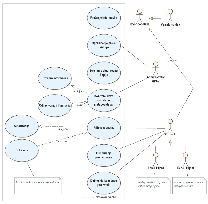
In the created Use Case diagram (Figure 1 andFigure 2) the spatial information comes from sources of information, which can be external systems (including systems involved in the regulation of the transport system, or the user of the system under certain conditions). The external systems are represented by a type of generalization relationship, which means inheritance to the actor, the source of information. The main idea of obtaining input information about a road accident can be divided into two aspects depending on the goals − collecting datasets for some period for the purpose of statistics and analysis and collecting information about a single road accident that occurred near real time. In the first case, the sources can be official agencies (in Bulgaria these are: Road Infrastructure Agency, State Road Safety Agency, Ministry of Interior). In the second case, from a conceptual point of view, data sources can be system users themselves (witnesses of the accident or law enforcement officers for example), as well as traffic police officers through video surveillance.
An important component such as the administration of access rights is affected. Who can access spatial datasets, products and services in different forms (for example, only viewing, editing, updating, accessing, etc.). This part is invariably related to the user's login to the system, using the two types of relationships that are possible between the cases − "include", in which the base case always requires the behavior of the included one, while the included one can be executed independently, and "extended", in which case the base can use the functionality of the “extended”, but is not required. For the second type of relations, a condition should be set to fulfill the additional case, as in the specific diagram which defines that there will be a rejection from the system if the user's license is not active. It should be noted that the actors do not represent a specific user, but a role that the user assumes (they are authorized to perform a use case associated with this role) (Seldi et al. 2015). The restriction of access rights, together with the creation of archival copies of the system and the provision of input control are activities associated with one component − GIS administrator. It should be noted that the actors may or may not be people (for example, a server or other application program), depending on the case.
Input data control is a topic that is extremely important for a quality geodata product, as data is one of the most expensive and time-consuming components in any GIS. Here it is linked to the metadata database defined by international standardization, in particular ISO 19 115 – Metadata. To objectively present the reality and correctly understand the information regarding the created conceptual models and used abstractions, documentation in the form of metadata should be created to allow the correct use of a resource. Also, from the point of view of facilitating the sharing and efficient use of geodata, in addition to the basic elements of metadata, it is important to provide a common basis for understanding geodata datasets, which can be done by applying the metadata standard and building sets of geodata metadata in accordance with it (Govorov 2008). ISO 19 115 defines the minimum quantity of metadata for each input dataset, mandatory and recommended components, etc. Moreover, the availability of the defined metadata set for each input dataset is a favorable prerequisite for all subsequent processes in the system − starting with data entry, ensuring their correct classification and structuring, ensuring topological connectivity, which is a key component of all spatial information services, the comprehensive processing of data in various forms and, of course, the correct exchange, meeting international standards and aiming at interoperability.
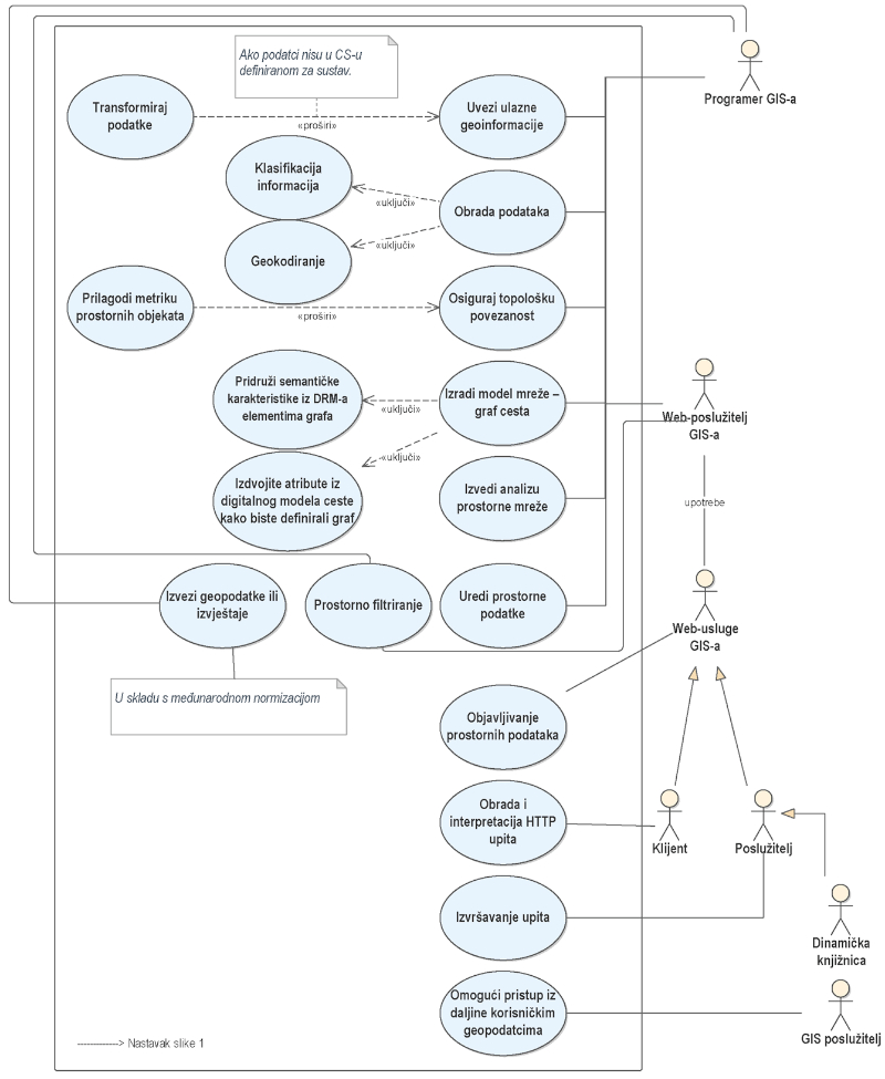
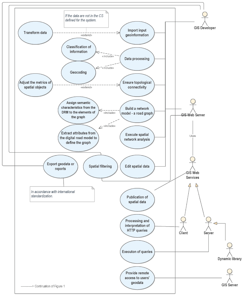
The system involves the division into two main major components – the desktop and server part. The specificity is that in both cases all the described functionalities for working with geodata are available. The difference is in the access of clients (which are differentiated into “thick” and “thin”), as well as in the software components involved in the processes of accessing and transferring information. On the server part, the final product reaches the customers through a web browser and includes the components − GIS Server, GIS Web Server and GIS Web Services. The responsibility of the GIS Server in the system is to provide system users with remote access to geodata or spatial databases, allowing the same data to be processed by any number of users who are connected to the server. The basic idea of this functionality is that the data is automatically updated for all users when making a change. The GIS Web Server is responsible for providing access to data based on GIS Web Services. It can also be considered an autonomous GIS, as it performs all its functionalities. GIS Web services, in turn, provide the connection between users and server applications. These are web services for publishing spatial data according to the protocols of the Open GIS Consortium (OGC) − Web Map Services (WMS), Web Map Tile Services (WMTS), Web Feature Services (WFS), Web Coverage Services (WCS) etc. The integration of these specifications is a key component as it provides unified access, search, processing, and exchange, creating opportunities for interaction between different systems. GIS Web Services has a client-server architecture, the client part of which is responsible for processing and interpreting HTTP requests, and the server − for processing client requests, analysis, and transmission for execution to dynamic libraries (Dimidenko et al. 2021).
The general functionality of the road accident GIS described in the Use Case diagram includes the development of a network digital road model by generating a road graph, the edges of which are given all available characteristics of road objects (number of lanes, different classifications, type of road pavement, etc.) (Dimidenko 2020). Another main activity is the use of some of these attributes to define the components of the road graph (for example, permitted speed, which can then be used in algorithmization for one of the main tasks with the graph − finding the shortest distance).
The diagram thus defined shows the user-system connections, data source-system connections, as well as the internal connections, indicating the typed information processes and differentiating the system into desktop and server.
Figure 1. Road Accident Use Case diagram Part 1
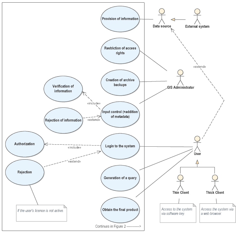
Figure 2. Road Accident Use Case diagram Part 2 (continuation ofFigure 1)
2.2. Class diagram
The applicability of the chosen objects by ISO modeling language, which achieves a complete and unambiguous definition of rules for structured description of a system − UML is objective since it is a language that supports OOP, allowing the creation of a real-world analogue. An essential property of OOP that is implemented through UML is that it can be used in the interaction of a complex program with users, elements, other programs and, of course, data (Sanders, Sanders 2007).
The created conceptual schema, presented by the class diagram, uses the OOP functionalities − inheritance-type relations are defined (one of the main and most important characteristics of OOP due to its function of reducing repeatability), aggregation and composition between different classes, and abstract classes are defined, the specificity of which is that they are not instantiated directly − only their subclasses are instantiated, which inherit the characteristics of their superclasses. It is important to note that all abstract classes are defined in italic font.
The starting point for creating the conceptual schema of a road accident GIS is the idea set out in (INSPIRE Thematic Working Group Transport Networks, 2014), which aims to achieve an integrated transport approach between different types of network transport infrastructures through the inherent ISO 19 100 extensible mechanism combined with single presentation of data and repeated usage.
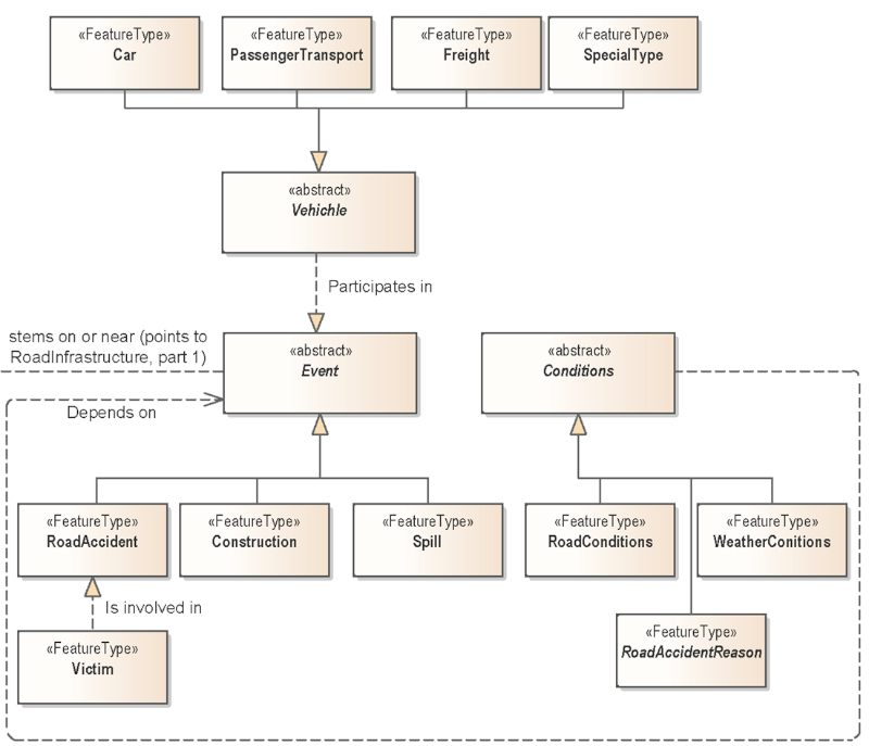
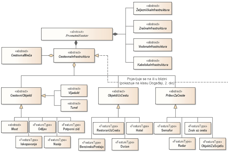
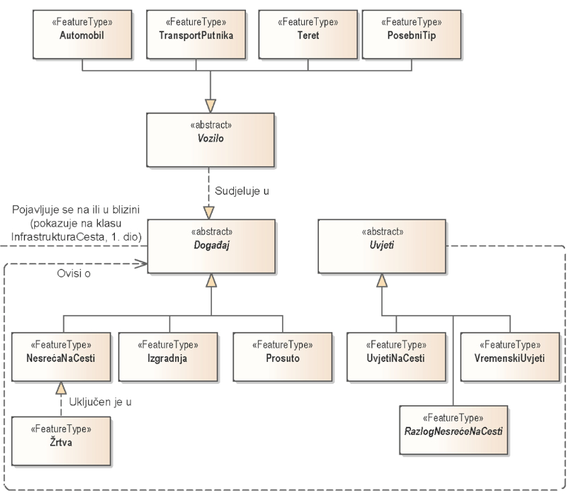
The overall model is differentiated into two submodels that are interconnected − road infrastructure and road accidents (Figure 3, (Figure 4).
For the road infrastructure feature classification, the normative regulation, valid for the territory of the Republic of Bulgaria and concerning the management, administration, construction, repair, maintenance and financing of the roads, as well as the management of the road infrastructure safety in the Republic of Bulgaria – Law of Roads in force since 11 August 2020 is used in combination with the accompanying regulations for its application and the current Ordinance for Large-scale topographic signs in scales 1:5000 and 1:10 000. In road accident classification in the classes, a causal relationship is defined by a detailed description of the causes and results of an event.
In general, the transport system consists of road, rail, air, water, and cable infrastructure. In turn, the road infrastructure consists of a road network, road facilities, road accessories and roadside facilities. The road network is presented as an abstract superclass of all types of roads − highways, national road network roads and others, where every different type of road is a separate class from which to instantiate objects in terms of future different visualization. The approach is similar for road facilities such as a bridge, tunnel, viaduct − a separate class is defined for different roads (for example, a motorway tunnel, a bridge on the road from the national road network, etc.). Due to figure size limitations, complete diagrams with all their components cannot be presented, so the main ones are described. Road accessories and roadside facilities are also defined as abstract classes in terms of the fact that the final collection of instances will be instantiated by their generalized subclasses − for example a specific traffic light, road sign or petrol station.
Road accidents are defined as a subclass with a relation of type generalization of a superclass Event. Repairs and spills are also classified as events occurring on or near the road infrastructure. Classes of vehicles and victims are defined, and they participate in the accidents class. A separate class of conditions is generated, the inheritor of which are road conditions and meteorological conditions. Successor to the class conditions are also reasons for/behind accidents.
Figure 3. Road Accident Elements of the Class diagram Part 1
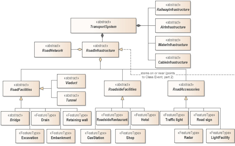
Figure 4. Road Accident Elements of the Class diagram Part 2 (continuation ofFigure 3)
