
1. INTRODUCTION / Uvod
The thrust force and its position are the results of the velocity field on the propeller. The velocity field depends on the shape of the ship's line, hull and stern, the construction of the propeller, the rudder and the different directions of navigation (ahead, astern, turning, stopping, starting, positioning, navigating in shallow or deep seas, rough seas, navigating with cargo loaded or empty, towing...). For this reason, the inflow velocity at the propeller is not the same at various points on the propeller surface [1].
In their paper, Tae-goo-Lee et al [2] emphasised the importance of analysing the velocity field at the propeller. They simulated a model of the ship's hull with a propeller when navigating straight ahead and when turning left and right. Based on the velocity field obtained, they analysed the loads on the propeller and their influence on the stern tube bearing load with the help of Computational Fluid Dynamics Simulation Software - CFD. During a sudden turning of the ship, extreme loads occur which are transmitted to the stern tube bearing [2,3] via the shaft of the ship's propeller, and which are 3-4 times higher than the nominal loads that occur when the ship is navigating in a straight ahead.
The loads absorbed by the bearing are important for the selection of the stern tube slide bearing and lubricant for lubrication as well as for the determination of other parameters of the stern tube bearing based on the theory of hydrodynamic lubrication. For further analysis, the load on the ship's propeller is replaced by the resulting thrust force, and depending of its position, there are changes in the geometry of the bearing. If these changes were to remain within the thickness of the lubricant layer of the stern tube slide bearing, mixed friction and consequential bearing wear would be avoided.
The magnitude of the resulting thrust force and its position affect the curvature of the elastic line of the sleeve in the stern tube bearing. Under normal conditions of straight ahead navigation (controlled conditions, sufficiently deep and calm seas), the position of the resulting thrust force is usually above the center of the propeller. The resulting moment straightens the elastic line of the stern tube bearing and the load on the bearing is reduced [2]. In the case of the ship turning, it is the other way around and the load on the bearing increases. This paper considers the influence of moving the ship straight ahead, turning her and moving her astern on the selection of stern tube slide bearing.
2. METHODOLOGY / Metodologija
2.1. Eccentric thrust force / Ekscentrična porivna sila
The resulting thrust force FT (hereafter referred to as "thrust force") with the position outside the center of the propeller is called the eccentric thrust force. It is obtained as the concentrated force by integrating the pressure field over the surface of the propeller and then dividing by its surface.
The Croatian Register of Shipping for the review calculations of the ship's propulsion shafting systems supposes that the thrust force FT is calculated to act perpendicular to the y- z plane of the propeller in a direction parallel to the x-axis of the shaft, and that its position is above the y-axis at the distance eT from the propeller center in amount of 4% of the propeller outer diameter D [4].
However, from what was said in the introduction, taking into account the variable velocity field on the ship's propeller, it follows that the position of the thrust force FT is variable and cannot be determined in advance, i.e. it can be anywhere on the surface of the propeller (Figure 1).
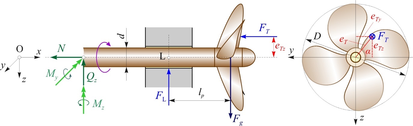
Figure 1 Theoretical load model of the stern tube slide bearing
Slika 1. Teoretski model opterećenja statvenog kliznog ležaja
In addition to the bending moment with respect to the point L generated by the weight of the propeller Fg (the self-weight of the shaft is neglected), there are also moments generated by the action of the thrust force FT with respect to its position, i.e.:
- moment about the y-axis, MLy :
(Nm) and (1)
- moment about the z-axis, MLz :
(Nm), (2)
where:
lp - length between propeller and stern tube slide bearing (m),
eTz and eTy - projections of the distance eT onto the z and y axes (m).
These moments MLy and MLz correspond to the spatial elasticity line of the shaft sleeve inside the stern tube bearing.
In the remainder of the paper, for the sake of simpler analysis, it was assumed that the positon of the thrust force FT is on the negative axis z for the case of straight ahead and astern navigation, and on the positive axis y for the case of turning of the ship. The amount of the distance eT according to the rule-of-thumb used by the Croatian Register of Shipping is assumed, i.e. eTz = eTy = eT = 4% D.
In this case, for further analysis, the moment of the eccentric thrust force is MP :
(Nm). (3)
2.2. Calculation of the thrust force / Proračun porivne sile
The thrust force FT produced by the propeller can be determined from the expression [5]:
(N), (4)
where:
PD - power delivered to propeller (kW),
va - advance speed (m/s),
ηo - open water propeller efficiency.
Power delivered to propeller PD can be determined from the expression [5]:
(kW), (5)
where:
PB - rated power of the main engine (kW),
ηs - shaft efficiency, which is:
0.95-0.98 for long shafts and if a reduction gear is installed.
Advance speed va can be determined from the expression [5]:
(m/s), (6)
where:
v - ship speed (m/s),
w - wake fraction coefficient, which is:
0.2-0.45 for the propeller arrangement as a single screw.
To calculate the geometric and hydrodynamic characteristics of the fixed pitch propellers, the Wageningen B series propellers are extensively used [6,7,8]. From typical propeller design diagram BP - δ it is possible to select values of the optimal open water propeller efficiency ηo and pitch ratio H/ D [8].
The design coefficient Bp is defined as [8]:
, (7)
while for the selected propeller diameter D, the design coefficient δ is defined as follows [8]:
. (8)
The expressions for the design coefficients (7) and (8) are adapted to the measurement units for: n - rated rotation speed of the propeller (in rpm), PD - power delivered to propeller (in kW), va - advance speed (in m/s) and D - propeller diameter (in m).
Values for the δ are reduced by 4-6% for the propeller arrangement as a single screw [7].
The magnitude of the thrust force FT can be controlled using the expression given by the Croatian Register of Shipping [9]:
(N), (9)
where:
P - rated power P = PB (kW),
H - mean propeller pitch (mm),
n - rated rotation speed of the propeller (rpm).
2.3. Simplified analytical model of the shaft line / Pojednostavljen analitički model vratilnog voda
The aim of the paper is to study justifiable engineering methods to facilitate the selection of the stern tube bearing, i.e. to create analytical models of shaft lines that allow the correct selection of the type of stern tube slide bearing. Therefore, it is necessary to find the suitable analytical model and eventually simplified expressions that can be used in the initial stage of stern tube bearing selection. In this way, the recommendation for the selection of the stern tube bearing could be made in a simplified way.
Figures 2 and 3 show the general models of shaft lines of ship propulsion systems with six (ABCDELP), five (ABDELP) and four (ADELP) supports, loaded by the weight of the propeller Fg and the moment of eccentric thrust force MP , which are analytically closest to the real models. The models are with one stern tube slide bearing, i.e. with the aft stern tube slide bearing [10,11]. Point P marks the position of the propeller, support L represents the aft stern tube slide bearing, support A represents the fore bearing of the prime mover (e.g. marine Diesel engine), while the other supports are radial support bearings of the intermediate shaft(s). The aim is to simplify the general model and limit it to two fields of the intermediate shaft of the shaft line towards the propeller in order to facilitate future calculations and analyses. To confirm the above, the simplified model is compared with the general model.
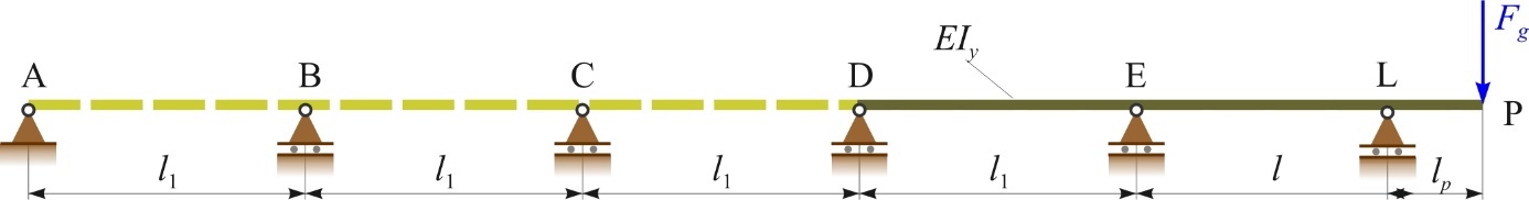
Figure 2 General model of the shaft line loading by the weight of the propeller Fg
Slika 2. Opći model vratilnog voda za slučaj opterećenja težinom brodskog vijka Fg
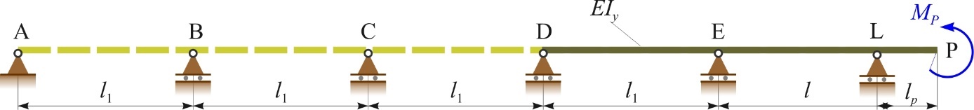
Figure 3 General model of the shaft line loading by the moment of eccentric thrust force MP
Slika 3. Opći model vratilnog voda za slučaj opterećenja momentom ekscentrične porivne sile MP
For the general model, an analysis of the influence of the number of supports (i.e. intermediate shafts) on the deflection of the shaft at the location of the propeller wP and on the slope of the elastic line of the shaft sleeve in the stern tube bearing βL was performed using the method of initial parameters (transfer matrix) [12]. The analysis covers the lengths of propeller shafts of the ship propulsion shaft lines determined by the expression according to the rules of the Croatian Register of Shipping [9]:
(m), (10)
where:
l - length of propeller shaft (length between the two aftmost bearings E and L) (m),
d - calculated diameter of the intermediate shaft (m),
λ - value of the factor, which is:
= 14 for n ≤ 500 rpm
= for n ≥ 500 rpm,
n - rated rotation speed of the propeller shaft (rpm).
According to the expression (10) for n ≤ 500 rpm and d ≤ 300 mm, the length between the two aftmost shafting bearings is: 3.012 ≤ l ≤ 7.668 m. In the paper, the calculation of the shaft deflection at the location of the propeller wP and the slope of the elastic line of the shaft sleeve in the stern tube bearing βL is given for equal amounts of the intermediate shaft length l1 = l of 3, 5 and 7 m [12]. The results obtained were compared with those obtained for the simplified models shown in Figures 4 and 5. The values from Section 3 were used for this calculation.
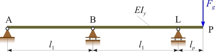
Figure 4 Simplified model of the shaft line loading by the weight of the propeller Fg
Slika 4. Pojednostavljen model vratilnog voda za slučaj opterećenja težinom brodskog vijka Fg
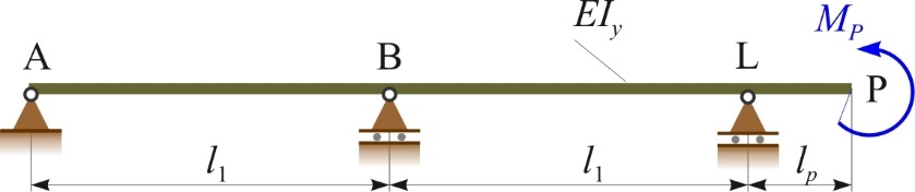
Figure 5 Simplified model of the shaft line loading by the moment of eccentric thrust force MP
Slika 5. Pojednostavljen model vratilnog voda za slučaj opterećenja momentom ekscentrične porivne sile MP
Tables 1 and 2 show the deviations of the shaft deflection at the location of the propeller and the slope of the elastic line of the shaft sleeve in the stern tube bearing of the simplified model in comparison with the general model (ABCDELP, ABDELP and ADELP) in the cases of loading by the weight of the propeller Fg and the moment of the eccentric thrust force MP . In the same tables, the results for the deflection of the shaft at the location of the propeller wPs and the slope of the elastic line of the shaft sleeve in the stern tube bearing βLs of the simplified model are given.
Table 1 Deviations of deflection and slope in the case of loading by the weight of the propeller Fg
Tablica 1. Odstupanja progiba i nagiba za slučaj opterećenja težinom brodskog vijka Fg
Table 2 Deviations of deflection and slope in the case of loading by the moment of the eccentric thrust force MP
Tablica 2. Odstupanja progiba i nagiba za slučaj opterećenja momentom ekscentrične porivne sile MP
Tables 1 and 2 show that the results for the deflection wPs and the slope βLs of the simplified model do not differ by more than 1% compared to the general model. Therefore, for further analysis of the influence of the external load (the weight of the propeller Fg and the moment of the eccentric thrust force MP ) on the elastic line of the shaft sleeve, the part of the shaft line towards the direction of the propeller is considered, exactly as shown in Figures 4 and 5. The rest of the shaft line in the direction of the ship's engine has no significant influence on the shape of the elastic line of the shaft sleeve in the stern tube bearing.
2.4. Deflection of the stern tube bearing sleeve / Progib rukavca statvenog ležaja
For the schematic representation of the elastic line of the shaft sleeve through the stern tube slide bearing with the relevant parameters, see Figure 6.
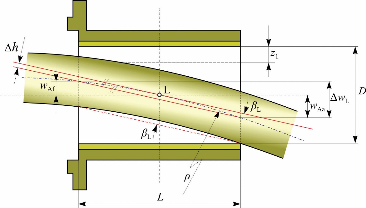
Figure 6 Elastic line of the shaft sleeve through the stern tube bearing
Slika 6. Elastična linija rukavca vratila kroz statveni ležaj
For the simplified model, an analysis of the deflection of the shaft sleeve in the stern tube bearing was carried out for different constructive characteristics of the bearing L/ D and the length of the intermediate shaft l1. The results of the deflection of the shaft sleeve in the forward wAf and aft wAa ends of the aft stern tube bearing, and the difference in the deflection of the shaft sleeve at the edges of the stern tube bearing Δ wL for the cases of loading of the shaft line by the weight of the propeller Fg and the moment of the eccentric thrust force MP can be obtained using the method of initial parameters [12].
From Figure 6 it can be concluded that the difference in the deflection of the shaft sleeve at the edges of the stern tube bearing Δ wL is equal to the product of the slope of the elastic line in the stern tube bearing βL and the length of the bearing itself L:
(mm), (11)
where:
βL - slope of the elastic line (rad).
The analysis resulted in an expression for calculating the deflection difference Δ wL,approx :
- in the case of loading by the weight of the propeller Fg :
(mm), (12)
- in the case of loading by the moment of the eccentric thrust force MP :
(mm) (13)
where:
Fg - propeller weight (N),
MP - moment of the eccentric thrust force (Nm),
E ∙ Iy - bending stiffness of the shaft (Nm2),
lp - length between the propeller and the stern tube bearing (m),
l1 - intermediate shaft length (m),
L - stern tube bearing length (mm).
Comparing the results obtained by the method of initial parameters and expressions (12) and (13), it can be concluded that the mentioned expressions can be used in the initial stage of the stern tube bearing selection for models of ship propulsion systems shaft lines with one (aft) stern tube bearing and with approximately equal lengths of intermediate shaft l1.
From them, the deflection values in the forward wAf and aft wAa ends of the stern tube bearing can be derived, assuming that:
(mm). (14)
The given methodology does not consider the influence of vibrations, but still enables an initial good selection of stern tube slide bearings, considering the impact of loads due to different navigation regimes on the wear of the bearing bush material and leakage of lubricant, which represents an environmental problem [13,14]. The analysis of the deflection values obtained by this methodology and their comparison with the expected minimum lubricant thickness h0 opens up the possibility of more correct selection of the stern tube bearing tribosystem in the initial stage. The aim is to ensure proper operation and energy efficiency of the shaft line (minimising frictional losses) and environmental acceptability (minimising lubricant leakage with particles of bearing bush material). The stern tube slide bearing selected this way should ensure optimal performance, long-term reliability and economic justification.
2.4. Procedure for the initial selection of the stern tube bearing / Procedura za početni odabir statvenog ležaja
The presented methodology is summarized with the procedure for the initial selection of the stern tube bearing. The input parameters required for this procedure are given in Table 3, while Table 4 contains expressions that must be followed for this purpose.
Table 3 Input parameters
Tablica 3. Ulazni parametri
Table 4 Output parameters
Tablica 4. Izlazni parametri
3. RESULTS AND DISCUSSION / Rezultati i rasprava
3.1. Calculation of the moment of the eccentric thrust force / Proračun momenta ekscentrične porivne sile
In this section the real example was used in further analysis. The ship is powered by a slow-speed Wärtsilä marine Diesel engine RT-flex35 with the maximal continuous rated power of PB = 3475 kW at the rotation speed of ne = 167 rpm [4]. The chosen diameter of the propeller shaft is d = 300 mm, so the diameter of the bearing is D = 300 mm. The modulus of elasticity of the shaft is E = 200 GPa, so its bending stiffness is E ∙ Iy = 79.522∙106 N/m2. The diameter of the propeller is D = 4 m, its weight is Fg = 100 kN, and it acts on the arm lP = 0.5 m with respect to the point L (Figure 1).
Power delivered to propeller if ηS = 0.95 according to expression (5) is PD = 3301.25 kW. Rated rotation speed of the propeller shaft (propeller) is n = 167 rpm (transmission ratio i = 1). Advance speed for the ship speed of v = 15 knots (7.717 m/s) and the wake fraction coefficient w = 0.2 according to expression (6) is va = 6.174 m/s.
For this analysis, the four blade fixed pitch propeller type B, series B.4.55. is selected [7]. According to expressions (7) and (8), the values for the design coefficients are Bp = 22.287 and δ = 171.676. From the BP - δ diagram, the values of the optimal open water propeller efficiency ηO = 0.59 and the pitch ratio H/ D = 0.95 (mean propeller pitch H = 3800 mm) were determined. The calculated thrust force according to expressions (8) and (9) is adopted as FT = 315 (kN) and the moment of the eccentric thrust force for the distance eT = 0.16 m according to expression (3) is adopted as MP = 50 kNm.
3.2. Comparison of deflection results applying the simplified model / Usporedba rezultata progiba primjenom pojednostavnjenog modela
Tables 5 and 6 show the results of the deflection of the shaft sleeve in the forward wAf and aft wAa ends of the aft stern tube bearing and the difference in the deflection of the shaft sleeve at the edges of the stern tube bearing Δ wL for the cases of loading of the shaft line by the weight of the propeller Fg (Figure 4) and by the moment of the eccentric thrust force MP (Figure 5) . The results of the deflection for different constructive characteristics of the bearing L/ D and the length of the intermediate shaft l1 were obtained using the method of initial parameters [12].
Table 5 Deflections wAf and wAa (mm) and the difference in deflection Δ wL (mm) for the case of loading by the weight of the propeller Fg
Tablica 5. Progibi wAf i wAa (mm) te razlika progiba ΔwL (mm) za slučaj opterećenja težinom brodskog vijka Fg
Table 6 Deflections wAf and wAa (mm) and the deflection difference Δ wL (mm) for the case of loading by the moment of the eccentric thrust force MP
Tablica 6. Progibi wAf i wAa (mm) te razlika progiba ΔwL (mm) za slučaj opterećenja momentom ekscentrične porivne sile MP
Using expressions (12) and (13), the obtained results of the difference in the deflection of the shaft sleeve at the edges of the stern tube bearing Δ wL,approx are listed in Tables 7 and 8 for the cases of loading of the shaft line by the weight of the propeller Fg and by the moment of the eccentric thrust force MP . Deviations from the results obtained by the method of initial parameters and expressions (12) and (13) are also listed in the Tables 7 and 8.
Table 7 Deviations of the deflection difference for the case of loading by the weight of the propeller Fg
Tablica 7. Odstupanja razlike progiba za slučaj opterećenja težinom brodskog vijka Fg
Table 8 Deviations of the deflection difference for the case of loading by the moment of the eccentric thrust force MP
Tablica 8. Odstupanja razlike progiba za slučaj opterećenja momentom ekscentrične porivne sile MP
The deviations in the above tables, for the case of loading by the weight of the propeller Fg of 3.15% and for the case of loading by the moment of the eccentric thrust force MP of 0.8%, confirm the sufficient accuracy of the results obtained with expressions (12) and (13). For the bearing with constructive characteristic L/D = 2 and the intermediate shaft length of l1 = 5 m, the deviations are below 1%.
3.3. The influence of the shaft sleeve elastic line on the selection of the stern tube bearing / Utjecaj elastične linije rukavca vratila na izbor statvenog ležaja
The correct selection of the aft stern tube bearing is the tribological problem. Its selection is strongly influenced by the eccentric thrust force. The change in the moment of the eccentric thrust force causes the change in the curvature of the elastic line of the shaft sleeve inside the stern tube bearing. It is important that these changes remain within the thickness of the lubricants layer h0, that is, there must be a minimum thickness of the lubricant layer. In this paper, the change of the elastic line for different positions of the thrust force FT is considered. For this analysis, the change in position of the thrust force FT is related to the navigating regime, as explained in the introduction. When navigating straight ahead and astern, the position of the thrust force FT is on the negative z-axis, while when turning it is on the positive y-axis (Figure 1). The results of the deflection of the shaft sleeve in the forward wAf and aft wAa end of the stern tube bearing were used (from Tables 5 and 6 or Tables 7 and 8) and they are compared with the values for the minimum thickness of the lubricant layer h0 from Table 9. It is necessary to discuss which stern tube bearing selection is favorable. The harmful impact of lubricating oil or polymer particles on the environment should also be considered. Table 9 shows the data for the minimum thickness of the lubricant layer h0 of the classic oil-lubricated and the polymer water-lubricated bearings determined for the real example analysed in this paper [4].
Table 9 Parameters of stern tube slide bearings with the contact angle Ω =360°
Tablica 9. Parametri statvenih kliznih ležajeva obuhvatnog kuta Ω =360o
The analysis was carried out for the constructive characteristic of the bearing L/D = 2 (length of the bearing is L = 600 mm) and the length of the intermediate shaft of l1 = 5 m.
Figures 7, 8 and 9 show the elastic lines of the shaft sleeve for the assumed positions of the thrust force FT of the navigation regimes mentioned. The values of deflection of the shaft sleeve at the edges of the stern tube bearing are given for: a) loading by the weight of the propeller Fg , b) loading by the moment of the eccentric thrust force MP and c) total loading. The previous alignment of the shaft line is not taken into account.
During normal straight ahead navigation (Figure 7), the moment of eccentric thrust force MP corrects the elastic line of the shaft sleeve caused by the weight of the propeller Fg , and fluid friction occurs in the stern tube slide bearing. The ship navigating at her steady-state speed of 15 knots. If such a regime is established and the sea during navigation is deep enough and also without significant waves, the thickness of the stern tube slide bearing lubricant layer is sufficient in relation to the curvature of the formed elastic line of the shaft sleeve (Figure 7c). In the case of minor disturbances in the navigation regime, the bearing enters the area of mixed friction. Hydrodynamic lubrication along the entire length of the bearing is achieved by adjusting the surface of the bearing and sleeve by running-in - wear.
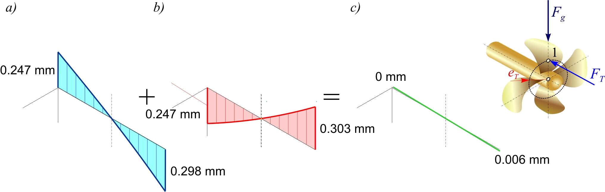
Figure 7 Elastic lines of the stern tube bearing sleeve for the case of navigating straight ahead
Slika 7. Elastične linije rukavca statvenog ležaja za slučaj plovidbe ravno naprijed
The turning of the ship during straight ahead navigation leads to changes in the curvature of the elastic line of the shaft sleeve inside the stern tube bearing (Figure 8). A greater thickness of lubricating oil is more suitable for these changes in the navigation regime. Here, edge wear occurs on the side surfaces of the aft and forward parts of the slide bearing bush (Figure 8c) and the stern tube slide bearing will enter the area of mixed friction [15].
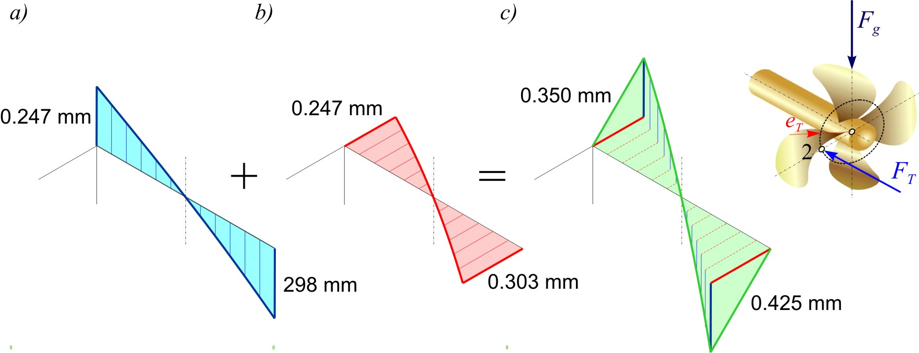
Figure 8 Elastic lines of the stern tube bearing sleeve for the case of turning
Slika 8. Elastične linije rukavca statvenog ležaja za slučaj skretanja
Strong disturbances in the operation of the stern tube bearing occur when the ship is navigating astern (Figure 9). Due to the greater resistance of the ship and the variable velocity field on the propeller, the equal amount of the thrust force FT = 315 kN is assumed for this analysis with the position of action on the negative z-axis. In this case, the aft part of the surface of the slide stern tube bearing bush wears due to elastic deformations and the deflection of the shaft sleeve caused by the weight of the propeller Fg and the moment of the eccentric thrust force MP (Figure 9c). It is possible that the stern tube slide bearing is in the transition area from mixed to semi-dry friction and vice versa.
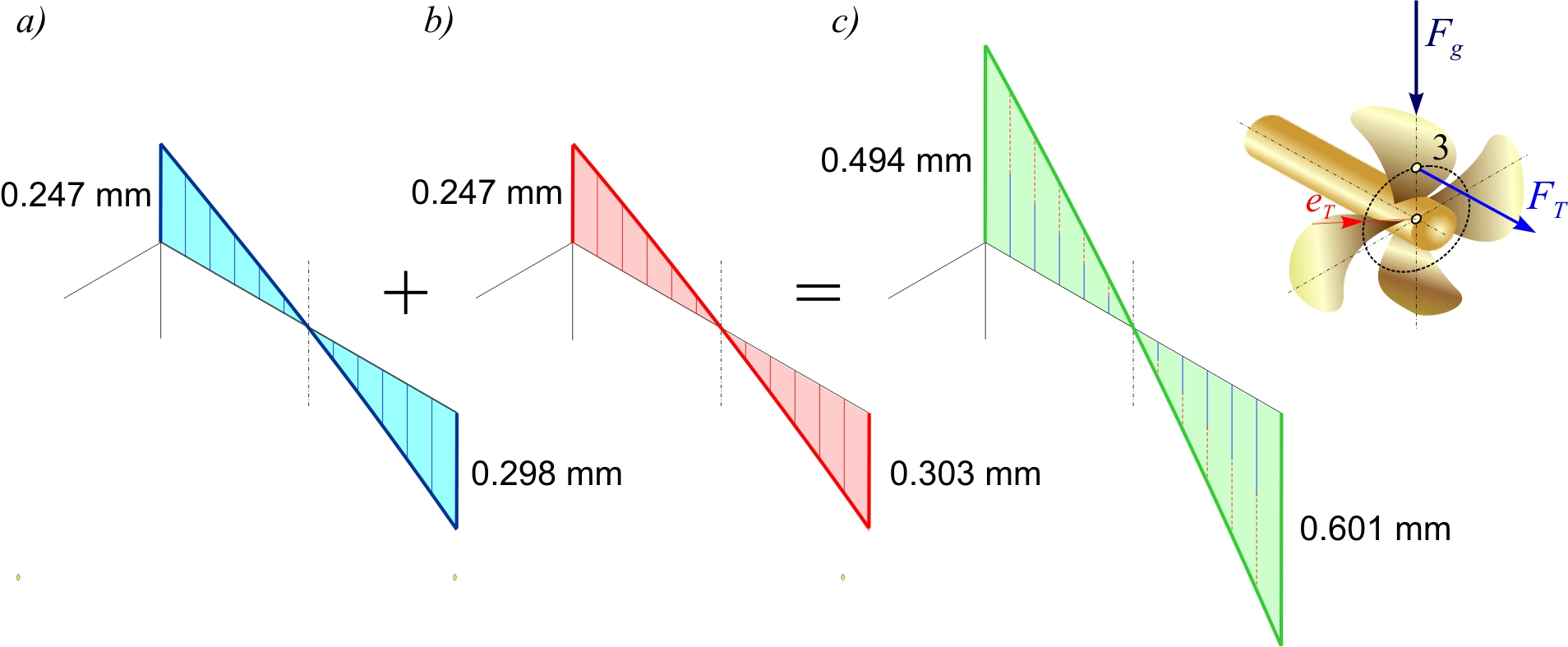
Figure 9 Elastic lines of the stern tube bearing sleeve for the case of navigating astern
Slika 9. Elastične linije rukavca statvenog ležaja za slučaj plovidbe krmom
The curvature of the elastic line of the shaft sleeve of the aft stern tube bearing, which is spatial in real cases, can sufficiently simulate the working area in which the stern tube slide bearing is located. The given diagrams, which are the result of simplified analytical models, show the state of the elastic line of the sleeve and the influence of its curvature on friction and wear of the material of the slide bearing bush for various cases of external loading. The calculated moment of the eccentric thrust force MP only for the case eT = 4%D, which was analyzed in this paper, already has a great influence on the working area of the stern tube bearing. Therefore, confirmation of the application of the simplified model is important for future analysis and research [16,17]. In this case, quick and reliable selection of the slide bearing bush and lubricant for the stern tube bearing lubrication can be expected.
4. CONCLUSIONS / Zaključci
The tribological system of the stern tube slide bearing must ensure the energy efficiency of the shaft line of the ship propulsion system and environmental sustainability. Various disturbances have a great influence on the correct operation of the stern tube slide bearing, i.e. on the hydrodynamic lubrication. One of them is different navigation regimes. The velocity field on the ship's propeller determines the magnitude of thrust force, but its point of action is even more important. The position of the thrust force on the surface of the propeller is variable and so is the moment of the eccentric thrust force, which usually corresponds to the spatial curvature of the elastic line of the shaft sleeve in the stern tube bearing. The change from navigating straight ahead to turning leads to a change in the curvature of the elastic line of the shaft sleeve and causes disturbances in the operation of the stern tube bearing, i.e. a transition from fluid to mixed friction. In this case, too, there is inevitable wear of the material of the slide bearing bush due to the adjustment of the curvature of the shaft sleeve, which has a harmful effect on the environment. In order to analyze the influence of the elastic line of the sleeve on the working area of the slide bearing as simply as possible, the aim is to provide fast analytical methods that would be good and reliable enough for the selection of slide bearing bush materials and lubricants for the lubrication of the stern tube bearing. The basic idea is to set up an analytical model with two fields of the shaft line that can be verified with a sufficiently large number of different geometries of the shaft lines of ship propulsion systems. In this way, the simplified model is expected to be created that covers also complex systems and provides results that are important for the selection of the stern tube bearing. Such a model is credible and suitable for broader application. In quantifying this simplified model with two shaft fields, the moment of the eccentric thrust force plays an important role and should be taken into account in the future development of the stern tube slide bearing testing device. With this upgrade, it would be possible to verify the results by testing on a device that can faithfully simulate the real situation of the stern tube bearing on a ship at sea and thus the real spatial curvature of the elastic line of the shaft sleeve in the stern tube slide bearing. A testing device based on a simplified model could contribute to the development of new materials, lubricants and constructive solutions of the stern tube bearing tribosystem.
Author Contributions: Conceptualization, V.V. and N.V.; Methodology, V.V.; Software, B.P.; Validation, V.V., N.V. and B.P.; Formal Analysis, V.V.; Investigation, V.V.; Resources, V.V.; Data Curation, V.V.; Writing – Original Draft Preparation, V.V.; Writing – Review & Editing, V.V.; Visualization, B.P.; Supervision, N.V.; Project Administration, V.V.; Funding Acquisition, V.V.
Funding: Founding for publication was obtained from the project "Functional integration of the University of Split, PMF-ST, PFST, and KTF-ST through the development of scientific research infrastructure in the Three Faculties Building", project no. KK.01.1.1.02.0018.
Conflict of interest: None.
Acknowledgments: The authors gratefully acknowledge financial support from the University of Split for this paper, which is realised under the project "Functional integration of the University of Split, PMF-ST, PFST, and KTF-ST through the development of scientific research infrastructure in the Three Faculties Building".