
INTRODUCTION
A single ladder, is as reported by many scientists, hazardous equipment for extending the human reach. Various ladder use incidents and consequently injuries occur in both environments, occupational and non-occupational[1][2], which is unfortunately, still the case. Among other findings is that sliding and cross section buckling are the main cause of ladder injuries, and most of available reported data/occurrence of ladder incidents and their consequences are about occupational incidents, but lacking to provide data for non-occupational incidents and consequent injuries. It was reported[3] that in 2005 in the USA 20 000 workers were injured and over 100 died as a result of falls from ladders. Another report[4] mention that in the USA in 2012 cost burden was 5,12 billion US dollars due to workers falls to lower level, which includes falls from ladders, and that ladder incidents persist to be major concern, despite improved standards and regulations. There are many different sources that confirm these statements and reports every year, but similar reports are not available worldwide to enable systematic problem overview, especially for non-occupational environments. Another possible restriction is that there are various types of ladder design that also may have its own ladder incidents reasoning, and may not have common causality for every ladder type in general. Another set of data not reported about ladder incidents are circumstances and environmental parameters, user’s age and personal psychophysical condition, experience, anthropometry, type of task performed and climbing technique, possible disturbances and so forth including true causes of reported incidents occurrence. Speculation about analysis of ladder use parameters (with respect to ladder purpose – a tool/equipment) that will reveal critical issues can be continued, but instead, our focus is on ladder usage model consisted of man, ladder, and environment. Each sub-element of this model has its own parameters that should be taken into consideration. From ergonomic perspective, non-occupational incidents may involve even more critical parameters than in occupational incidents since occupational users are assumed to have necessary psychophysical abilities, experience, training and awareness of appropriate standards and regulations and are familiar with proper ladder settings and their utilization, unlike most non-occupational users. Such perspective supports our safety concern about ladder use, especially for non-occupational environments, that is in focus in this article. Hence, safe ladder utilization implies various parameters to be properly applied during user ladder ascent and descent, and of course, task completion. Many scientists have investigated how climbers (workers) set up the ladder, in context of the recommended inclination angle of 75,5°. Average angle achieved in real life situations is below 75,5°, mostly around 70°. In 49 % of straight ladder incidents, the inclined angle was less than 65°[5]. Articles concerning the ladder climbing safety report dynamics of climbing measured by a dynamometer, some kind of scales[1][6], or with Inertial Measurement Unit (IMU) supported analysis[7]. IMU supported analysis[7] considered aspects of biomechanical analysis during ladder ascent with objective to identify musculoskeletal stresses that might explain possible risks and hazards. Numerically addressed ladder problem[8] considered taking into account physics and mechanical modelling of ladder behaviour, however, other elements of the system were neglected. Further,[9] analysed effects of aerial ladder rung spacing on firefighter climbing biomechanics, with conclusion that reduced rung spacing may lead to lower biomechanical stress, better climbing efficiency and safety and reduced climbing speed disparity across sexes. Such finding connects anthropometrical data with ladder design thatopened speculation about optimal relation – what is the best fit of the man to the task, and consequently, the ladder design. From systematized gathered findings with preceding researches[9] can be recognized that most of the reports are about occupational environments and ladder utilization. Comprehension of hazards related to ladder use implies that specific variables exist in the ladder use that can be identified as critical – that affects safety, where other parameters of the user-ladder system may be considered as variables that vary the utilization efficacy. Anyhow, all-inclusive policy should be supported, with regard to safety of all potential users. It is obvious that ladder stability is the first priority to be achieved, that can be compromised by ascent dynamics, ladder setup/slant and its design, beside other environmental and utilization conditions. Regarding ladder stability, it is comprehended as dynamics of ladder behaviour throughout its utilization where ladder ground contact support forces remain within acceptable margins, along with absence of ladder rotation (which may be caused by or can cause sliding movement – frontal or/and sagittal), with appropriate structural integrity. However, although stability priority covers issues with structural integrity as another important perspective of the problem, it is not within the scope of this article. This article will address non-occupational users and ladder design utilization, where numerical modelling will be employed. Objective is to review critical conditions of ladder use by temporospatial ladder stability analysis when biomechanical considerations are also integrated – with respect to human body kinematics and dynamics. In viewing the ascent on single ladder as a rigid body, or construction, available references do not report sagittal climber’s centre of mass trajectory in correlation with a function of time, ascent dynamics nor their impact on ladder stability, which was consider that matters. Expected ladder ascent and use of computational modelling results should reveal true ergonomic and biomechanical challenges, safety adjustments and revise available recommendations for potential ladder user, both occupational and non-occupational. Such contribution will enable proper ladder design, structural analysis and consequently will advance ladder use in order to contribute to better safety of use, lesser accidents occurrence and fatal consequences.
METHODS AND MATERIALS
As defined earlier, single ladder use model is considered to be composed of a person (who will climb the ladder to extend his reach), ladder (its design and specifications), and environment (ground and vertical wall, as physical contacts of slant ladder). LADDER MODEL A single ladder hereon denoted as a rigid body, is designed with two longitudinal main beams connected with step beams (transverse beams), rungs. Main beams can be set so that their transverse distance is constant, or decreasing along the longitudinal ladder axis, in ascent direction. It is assumed that single ladder will be positioned on the firm ground and inclined toward vertical wall. Ladder position is considered to achieve symmetrical contacts with respect to ladder longitudinal axis – there is no lateral inclination (at least in this article). Hence, central sagittal ladder plane is used as reference plane. Ladder slant angle is determined as angle achieved between ladder longitudinal axis and the horizontal ground plane in the central sagittal plane, in literature also defined as inclination angle between ladder axis and the ground/floor plane. Since one of the objectives was to revise non-occupational parameters of ladder use, commercially available single aluminium ladder were taken as geometric model for computation. The ladder’s mass is 14,2 kg, actual rung spacing is 0,28 m (11 in) and total ladder length is 5 m (16 ft. 5 in). Rung distance and ladder width are fixed. Moreover, created ladder model should enable adjustments of rung distance, and can be used for analysis of ladders with parallel and non-parallel main beams. LADDER CLIMB STYLE The base for calculating climber’s centre of gravity (CoG) and its biomechanics is the climbing style, which implies maintenance of a 3 point contact during each step that is presumed to be completed with identical kinematics. Ladder climbing requires full body coordination to maintain points of contact using both upper body and lower body. Previous research has indicated an overlap between hand contact and foot contact with the ladder[1][3]. . Assumption that central sagittal plane (CSP) is the plane of climbers CoG trajectory has been embraced since if movement trajectories of arms and legs remain in sagittal planes approximate to the CSP, CoG will be most distant from ladder longitudinal axis, which is recognized as the most unfavourable case of movement along the ladder. Moreover, even if that would not be the case, most of the CoG motion will still remain close to CSP, hence lateral climb perspective represents most appropriate presentation of climbing activities, depicted in Figure 1.
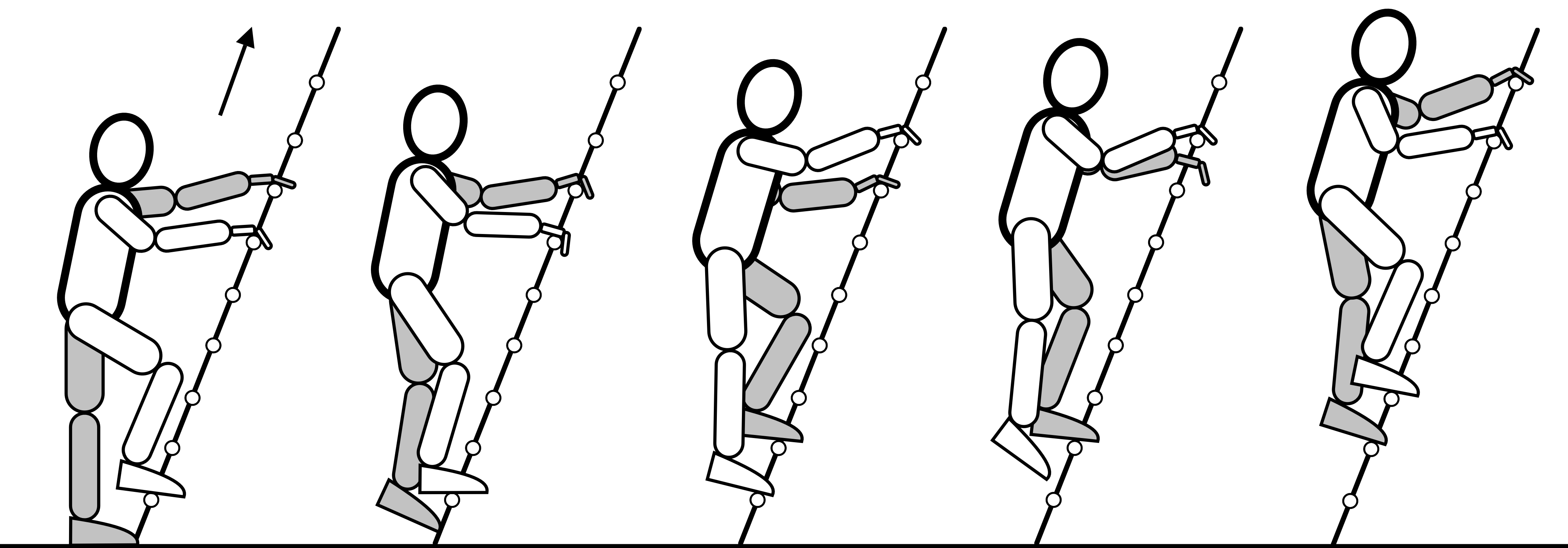
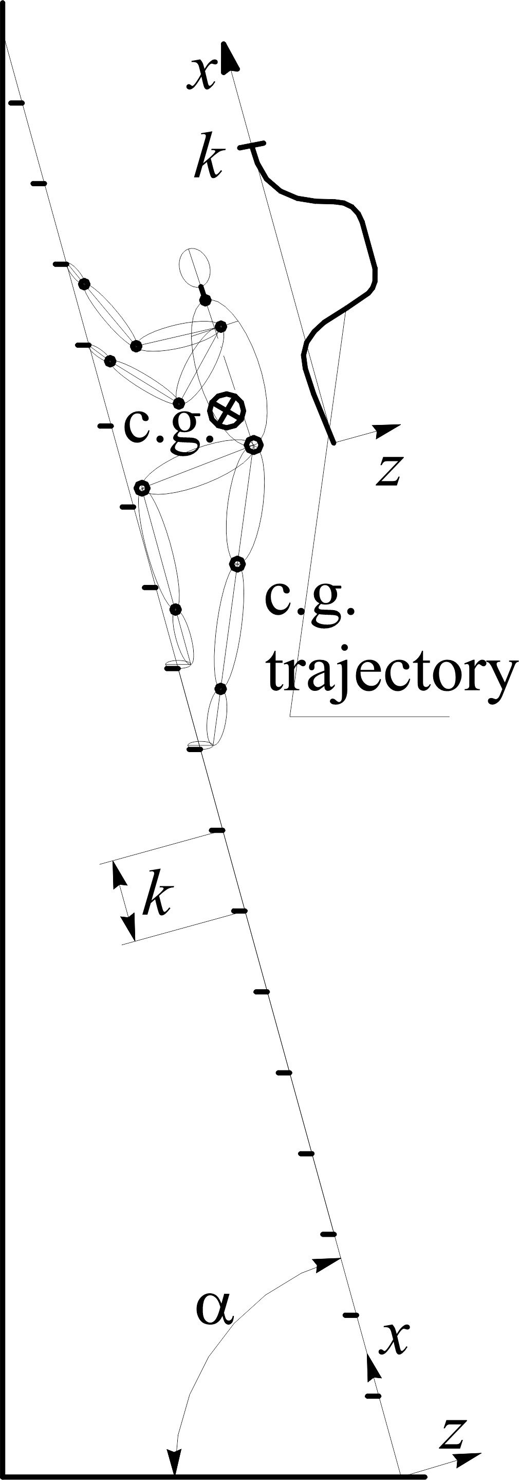
Ladder ascent is defined as a process starting from the resting stand, followed by acceleration, deceleration and stopping with resultant displacement of the body CoG along the length of the ladder for a single rung. Ascent is discretized in 10 steps, i.e. positions. Resting stand assumes one leg extended, while other leg rests on the first subsequent rung and with hands grasping the rungs at appropriate level. For the purpose of biomechanical modelling of ladder climb, the human body movements have been represented by CoG trajectory (Figure 2a) that is calculated for each discretized step, with respect to climber body segments position throughout the process of analysed climbing, using reported methodology for calculating CoG[10][11][12]. In the following calculation a climber height as 1,7 m and variable body mass is being considered. The authors themselves have verified that climber’s height of 1,7 m leads to arms – legs span (distance from middle of hands grasping rungs and middle of feet leaning rungs with given rung spacing in climb) of 1,4 m (4 ft. 7 in). The climber’s mass has been normalized to a 50th percentile of males average mass of age 20 and above in USA[13]. Based on the calculated trajectory, CoG is then approximated by a function of time to serve for calculating dynamics at any desired position, i.e. time in the ascent cycle.
ASCENT HUMAN BODY KINEMATICS AND DYNAMICS
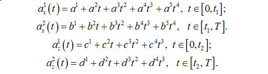
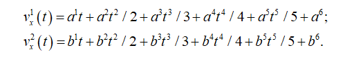
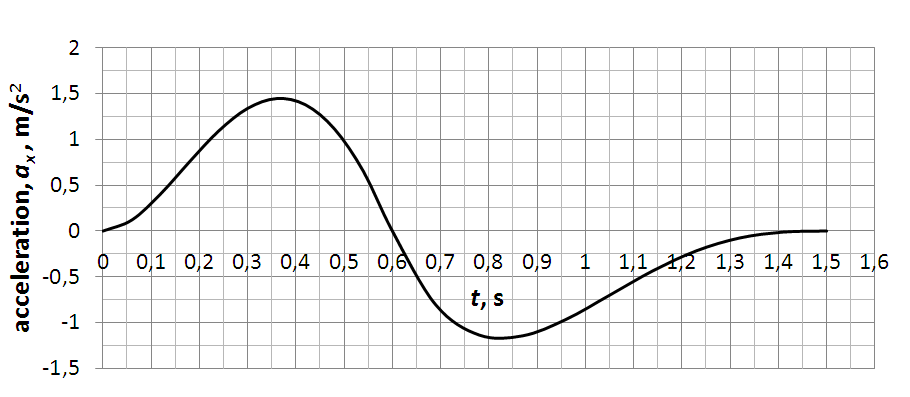
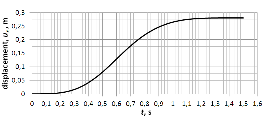
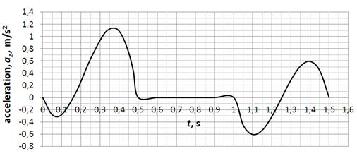
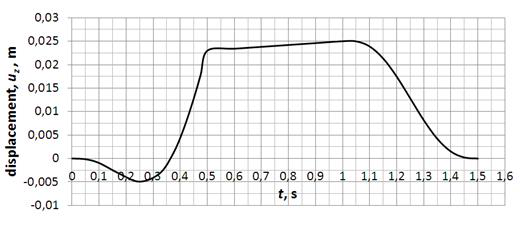
Kinematics is defined with the calculated CoG and adopted climbing cycle duration[3][4][5][6][7][8][9][10][11][12][13][14] with suggested duration of mild and intensive climbing cycle to be 1,5 s and 1,0 s, respectively. With that information, the kinematics in components on coordinate axes x and z (along and perpendicular to the ladder, respectfully) is described with interpolating polynomials by parts of ascent cycle (as will be described latter) as functions of time. Firstly, the acceleration components are approximated, with degree of a polynomial chosen with respect to the total number of boundary and continuous conditions, than velocity as integrated function of acceleration, and displacement as integrated function of velocity. All functions (i.e. coefficients) have been determined by solving system of equations. Geometrical relations with regard to climbing dynamics will be used as model to present and calculate reaction forces on the wall and floor contact points in estimation of forces. At each time sequence, using the calculated climber’s CoG kinematics and dynamics (shown in Figure 2b and Figure 2c, inertial force components are calculated, combined climber and ladder weight (which form a new line at each time sequence), a force polygon is constructed. Combined weights and inertia force form an active load force on the ladder. The wall reaction force has a predetermined line of action because it is expected that in all the considered cases of ascent the ladder sliding away from the wall is the tendency of motion, hence the sliding downwards determines the direction of the friction force on the wall contact point. It is assumed that the friction force on the wall is at its maximum, i.e. the angle of that reaction is A = atan(A). Angles between the forces in the polygon are determined from the geometry, i.e. intersections of force lines. With determined acceleration and displacement functions, reactions on the wall and floor are then calculated in order to assess both of the safety conditions; separation from the wall and sliding on the floor. From those results a diagram with limit curves for both safety conditions is constructed. In that diagram curves show where is the limit between safe and unsafe zone, in sense of slant angle vs. friction coefficient and climber’s mass for a chosen climb period duration. In the kinematics approximation scheme the first step is to approximate the form of acceleration in the x and z axis, respectfully, according to fig. 3a) and 3c). It is chosen that the components of acceleration through the climbing cycle will be described in 2 parts, for each coordinate axis differently. For the x axis the first part, 𝑎𝑥 1 , is in the time limits t [0, t1], in which it is presumed that person climbing is increasing the velocity, and the second, 𝑎𝑥 2, in the time limits t [t1, T], with T being the cycle (period) duration, in which the person is decreasing velocity. For the z axis the first part, 𝑎𝑧 1, is in the time limits t [0, t2], and the second, 𝑎𝑧 2, in the time limits t [t2, T]. The approximated acceleration functions of time by parts are of shape
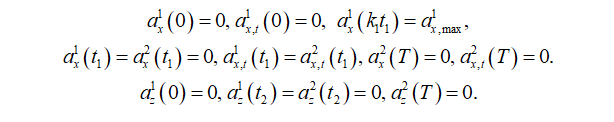
Several initial and continuous conditions on the acceleration functions have been imposed. Given the total number of kinematic conditions that can be imposed on the functions of acceleration, velocity and displacement, shown in detail further on, a variable point in the first part of the period (0 < ta < t1) is chosen, in which a value for acceleration is imposed to control the shape of the function. That time is defined as t(ax, max) = k1t1. The value of acceleration is denoted as “max”, however, it is not necessarily the maximum value, rather a control value. These conditions are as follows:
Integrating over time the function of acceleration gives function of velocity as follows
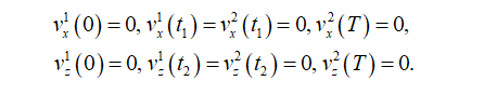
For velocity the boundary and continuous conditions are
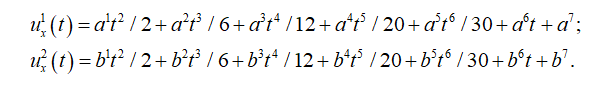
Integrating over time the function of velocity gives function of displacement as follows
For displacement, the boundary and continuity conditions are
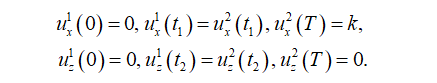
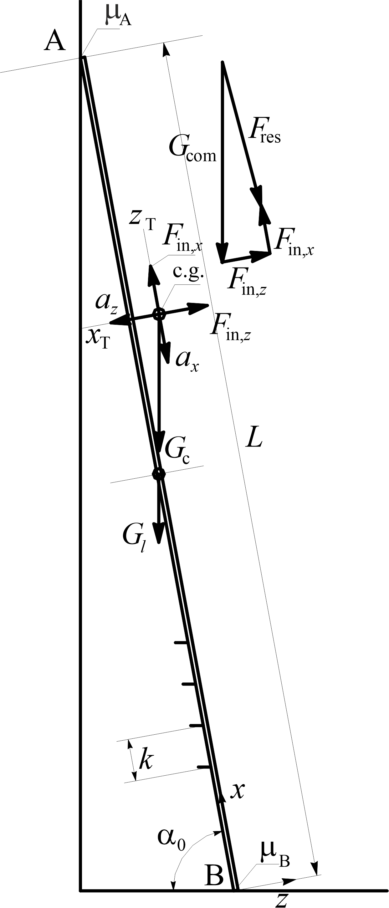
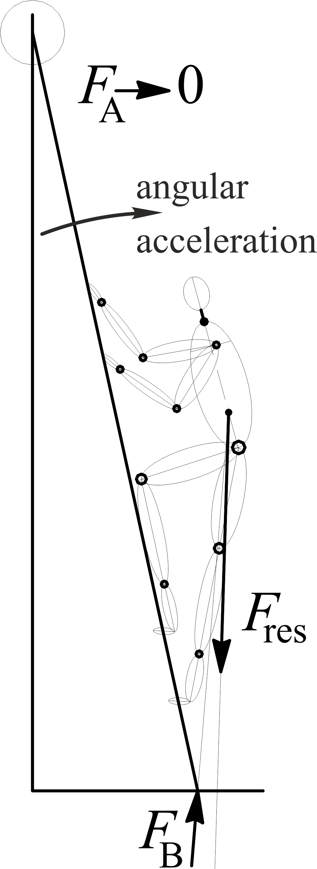
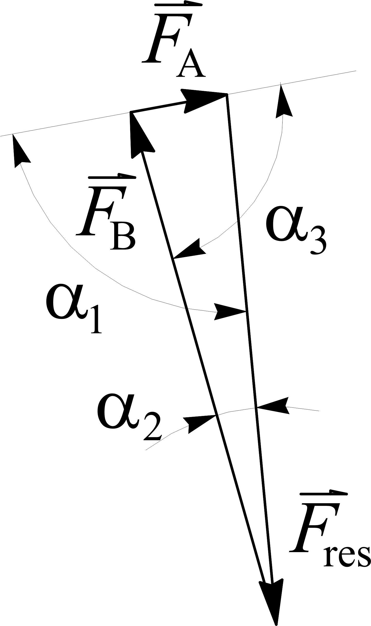
In (6) the index k denotes the rung spacing. Equations (1) through (6) form a system of equations, and after solving it, the kinematics components calculated are shown in Figure 3. For brevity, only kinematics components for cycle with T = 1,5 s are shown. Kinematics of cycle with T = 1,0 s is similar in shape, with different maximum and minimum values of acceleration. After calculating kinematics, dynamics is used to calculate load on the ladder. Combined displacements on the x axis vs. time and on the z axis vs. time give CoG trajectory, now as a continuous function of time. Symbolically, trajectory of the climber’s CoG is shown in Figure 2a. The inertial force is described, i.e. calculated, by two components, depicted with Fin,x and Fin,z, in Figure 2b. Each inertial force component is calculated as 𝐹 ⃗ 𝑖𝑛,𝑖 = −𝑚𝑐𝑎⃗𝑖, with i being coordinate axis index. Resultant of the inertial force components with the combined climber and ladder weights, denoted Gcom , form a ladder resultant load force denoted Fres . In Figure 2c line of the resultant force is then used to determine intersection with the line of the wall resting point reaction force, denoted FA, and by that intersection line of the floor resting point reaction force, denoted FB, is determined, shown in Figure 2c. In the same figure the range of the reaction (friction) force (friction angle) is shown with hatched triangles at each resting point. It is presumed that at each ascent cycle maximum of the friction force on the wall resting point (denoted A) is achieved, hence, it determines the angle of the reaction force line. It is also presumed that all the forces act in the ladder – climber system sagittal (symmetry) plane. The force polygon is then used to calculate reaction forces at each resting point by means of the vector equilibrium equation

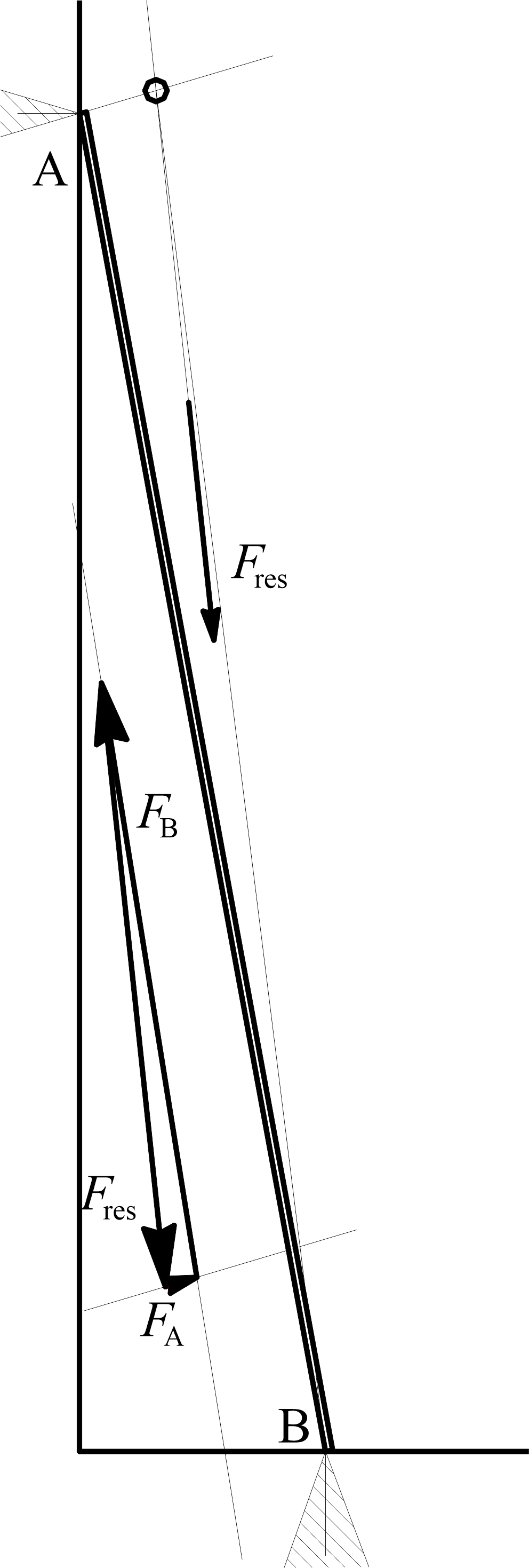
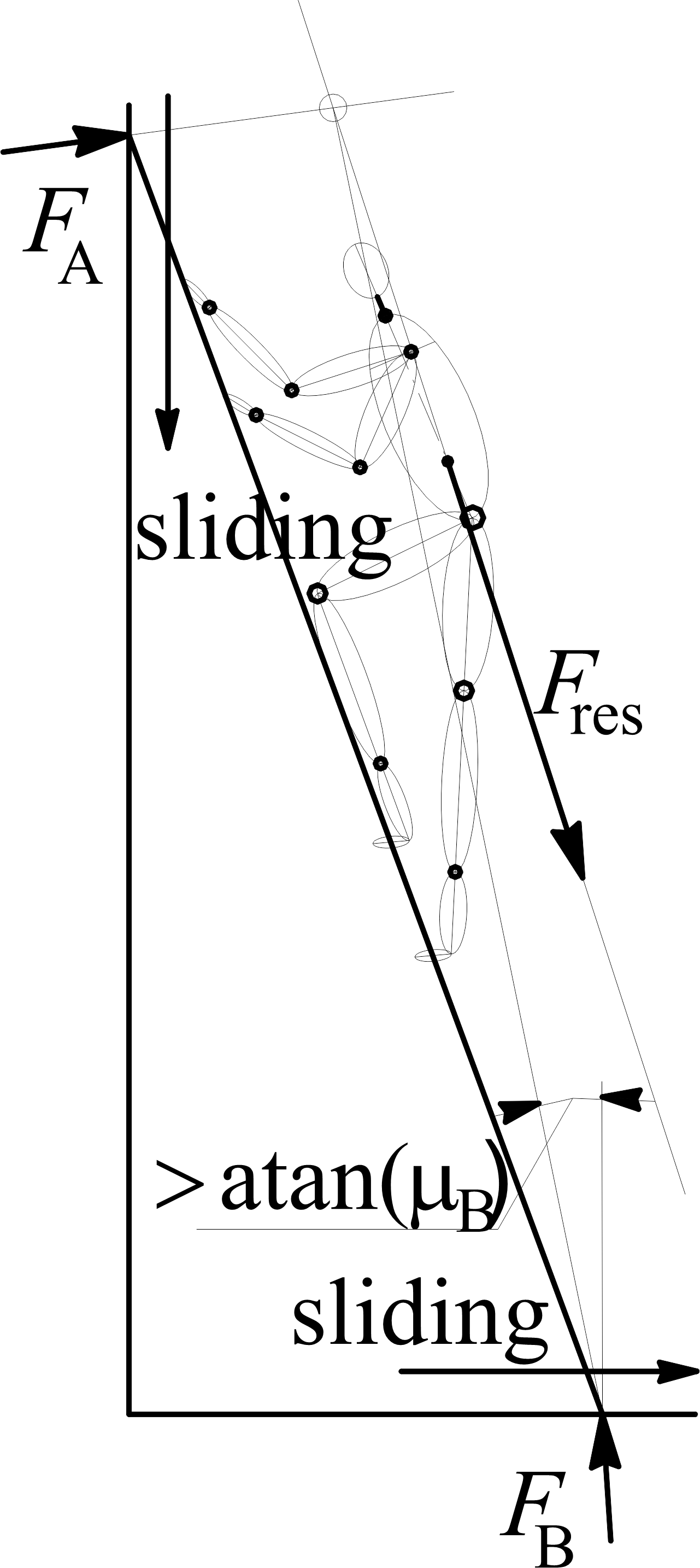
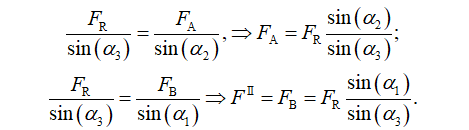
Based on the calculated reaction forces, a safety conditions are determined: separation from the wall, shown schematically in Figure 2d, and safety condition sliding on the floor, shown schematically in Figure 2e. The separation from the wall condition occurs when the reaction FA is zero or less than zero, i.e. angular acceleration which leads to rotation of ladders clock wise in Figure 2d begins. The sliding on the floor condition occurs when friction force on the floor contact point is insufficient to balance action of the climber, and the angular acceleration counter-clock wise in Figure 2e begins. In Figure 3a climber’s CoG acceleration on the x axis calculated after solving system of equations (1) through (6) is shown, as a function of time. Figure 3b shows climber’s CoG or displacement along the x axis, as a function of time. In Figure 3c climber’s CoG acceleration on the z axis is shown, as a function of time. Figure 3d shows climber’s CoG or displacement along the z axis, as a function of time. The three forces forming a closed polygon are shown in Figure 4. Reaction forces are calculated from Figure 4 using the sine theorem as
Time step taken in all the analysis of climbing dynamics, i.e. safety assessment was t = 0,03 s for the mild climbing kinematics, and t 0,02 s for the intense climbing kinematics. For the assesment of safety in climbing activity, two criterias will be used; the first, will the climber act in such a way on the ladder to cause zero reaction on the wall, i.e. beginning to separate from the wall, and the second, if the friction force on the floor contact point, FB, is insufficient to hold the ladder - climber system from sliding the point B away from the wall. Combination of parameters normalized climber’s mass mc, ascent cycle duration T, coefficient of friction on the floor, B, used in the analysis, gave values for the safety conditions. In each time sequence (step) reaction forces have been calculated according to equation (8) based on kinematics and dynamics, and the safety conditions in sense of the minimum inclination angle for sliding, and maximum for separation from the wall abstracted. The results of this analysis are shown in diagrams in Figures 6 and 7. The two climbing kinematics, with T = 1,5 s as mild, and T = 1,0 s as intense, analysed, gave results “condensed” into curves in diagrams in Figures 6 and 7. Both of the diagrams have an “upper” boundary curve, which gives relationship between the ladder inclination angle at which for a given normalized climber’s mass and climbing cycle duration the wall reaction is zero or less, and separation from the wall begins. All the other curves in a diagram represent a boundary between the conditions with “enough” friction force to hold the ladder in static state, which is coefficient of friction on the floor and “allowed” slant angle below which safety from sliding is lost. This is explained in Figure 5 on just one curve for sliding condition. In a diagram for a chosen cycle duration, and friction coefficient on the floor, i.e. the measured or estimated in reality, the normalized climber’s mass is parameter for which there are two curves which give intersections with line mnorm. One curve in diagram in Figure 5 is “lower”, denoted B = 0,25, dashed, and the other is “upper”, full (continuous). The upper boundary value for the inclination angle for mnorm = 0,9 for instance, is around 78° (separation from the wall above that angle), and lower boundary value is around 67° (below which sliding on the floor occurs). Between those two values is the “safe” range for the slant angle. In Figures 6 and 7 all of the dashed curves represent boundary curves for sliding on the floor safety condition. For a given set of remaining parameters, as the friction coefficient rises, the
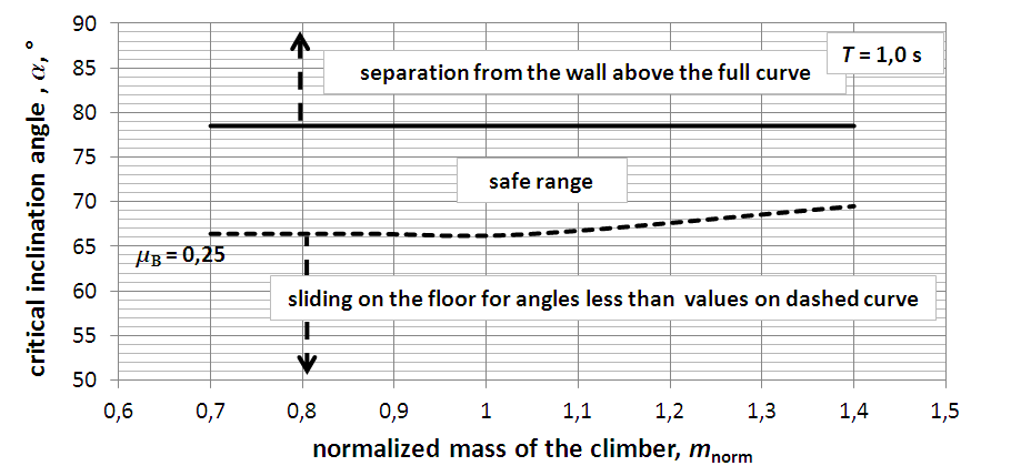
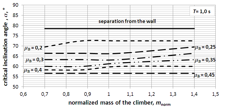
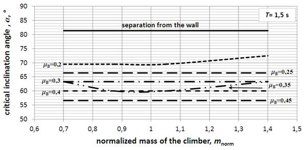
minimum inclination angle lowers, as expected. Curves give the same “recommendations”, or conclusion that the inclination angle of 75,5° is optimal for safe climbing in the described style (knees “within” the side rails) with described kinematics, with a low friction on the floor.
CONCLUSION
Primary goal of this article is to assess single rigid ladder stability in case of most unfavourable ascent style, with consideration of real time kinetics and kinematics, anthropometry of climber and variable contact friction factors. Ladder use model is defined as formed by a person, ladder, and environment. Analysis conducted confirmed our holistic consideration of the ladder use, and correspond to findings of others[6][7][9]. The kinematics of CoG has been described explicitly by interpolating polynomials by parts of ascent cycle, as a function of time. Displacement of CoG is described respectfully for each coordinate axis, i.e., along and perpendicular to the ladder longitudinal axis. Results presented show how body kinematics reflects on safety assessment of ladder climbing dynamics. Described CoG trajectory, estimated as primarily sagittal motion, is employed to calculate dynamics of single ladder climbing, and based on the reactions on the wall and floor assess safety conditions. The two safety conditions considered are: separation from the wall, and sliding on the floor. Variable friction coefficients on the floor contact point have been considered, ranging from 0,2 to 0,45. Slant angle of 75,5° can be found in recommended regulations and scholar publications[6][14][15] as the safest ladder slant angle which is confirmed by this article. Within the results presented, safe ladder slant angle is determined to range from 73° to 78° that considered a wide range of friction coefficients on the floor (from 0,2 and up), climber’ mass and climbing ascent cycle duration, which also shows validity of the proposed kinematics description. This way, our objective to assess rigid ladder stability with variable use parameters has resulted with relevant comprehensions. Secondary goal of this article was to validate created computational ladder utilization model and generated equations. Performed analysis of rigid single ladder usage affirmed validity of created computational ladder model and representative equations, which confirmed secondary goal accomplishment and ability to revise ladder use recommendations. Moreover, since analysis results confirmed compatibility with results of others[7][8][9], created model is expected to enable further extension of ladder use parameters to be considered and analysed. Hence, inclusivity of wider range of parameters of ladder use is expected to reveal other underestimated or neglected factors that might appear as critical ones. Author’s prospective future scope is introduction of deformability of the side rails, i.e. taking vibrations into consideration, which will extend and enable more complex structural integrity analysis and ladder design evaluation.