
1. Introduction
Numerical modelling is essential for studying the fundamental processes occurring in rocks, for assessing the predicted and actual performance of structures built on and in rock masses (Jing and Hudson, 2002). Therefore, the application of numerical analysis is of great interest and importance for design procedures as well as for confirming the use of various analytical methods to verify the local stability, and especially the global state of stability of mining structures. Due to the very complex nature of rock masses, consisting mainly of inhomogeneous, discontinuous, and anisotropic media, rock masses represent difficult geological material for mathematical representation through modelling, and therefore various numerical modelling techniques and methods have been developed (Jing, 2003).
A characteristic example of 3D numerical modelling of fractured rock mass excavation in an underground ornamental stone quarry was presented by Segalini et al. (2006). In this stability analysis, the rock mass was taken as a discontinuum and the numerical modelling was performed using the 3DEC computer programme (Itasca Consulting Group), based on the distinct (discrete) element method. In contrast, numerical modelling of underground storage caverns in soft rock was presented by Sari (2022), where the rock mass was treated as an equivalent continuum. Stability analyses of 2D and 3D models were performed using RS2 and RS3 computer programmes (Rocscience Inc.) based on the finite element method. In these numerical analyses, as in many others, it should be emphasised that the basis of numerical modelling is the conceptual model of the rock mass with all its parameters. It should be remembered that the accuracy of any predictions made using numerical modelling is ultimately strictly limited by the natural variability of the geologic materials (Wiles, 2006). For this reason, the results of numerical modelling are often compared with simple or empirical analytical solutions, especially in the design of individual structural elements, as in the design of rooms and pillars in the underground excavation mining method (Kun, 2014).
Special attention has been paid to the determination of pillar strength (Martin and Maybee, 2000; Gonzalez-Nicieza et al., 2006; Esterhuizen et al., 2011), since pillar strength depends on the strength of the rock mass and, in particular, on the pillar scale and size effect. Finally, a great contribution to the understanding of the rock pillar failure mechanism in underground openings was achieved by a numerical investigation presented by Mortazavi et al. (2009) and Suner & Tulu (2022).
Underground excavation of dimension stones using modern excavation technology started in Croatia with trial exploitation in the “Kanfanar” Quarry in 1995 (Cotman, 1996). With the aim of designing underground spaces, the first numerical analyses were performed using the 2D computer programme FLAC (Kovačević Zelić et al., 1996). Based on the experience and positive results of the trial underground exploitation and the results of numerical analyses, underground exploitation of dimension stones was designed on the same field and started in 1997 (Cotman and Vujec, 1998). In layered deposits with vertical and near-vertical cracks, as is the case in the “Kanfanar” Quarry, the room and pillar method of excavation with irregular distribution of pillars proved to be the most suitable mining method (Cotman and Vujec, 2005). The basic principle in this method is that the part of the rock mass that does not have cracks is excavated, and the part of the rock mass with cracks remains in the pillars, resulting in an irregular distribution of pillars. In this situation, the design of underground rooms, which includes the estimation of the maximum possible width of the rooms and the minimum size of the pillars, requires special attention.
In order to evaluate this mining method with respect to the stability of the underground spaces, extensive studies were carried out consisting of laboratory determination of the material properties of intact rock, in situ determination of the stresses and deformation modulus of the rock masses, as well as monitoring of the room convergences, displacements at the cracks and stress changes in the pillars. Subsequently, numerical analyses were performed for the underground excavation in the selected area during these investigations. The numerical analyses were carried out with the SAP2000 computer programme to create a model with the distribution and dimensions of the pillars and excavation phases corresponding to the actual situation in the selected area. Through this modelling, a very good agreement was obtained between the results of the in-situ tests and measurements and the results of the numerical analyses (Hrženjak et al., 2019). However, the analysis of the underground quarry with the designed maximum dimensions of the rooms and their influence on the redistribution of stresses in the rock masses around the quarry has not yet been carried out. With the aim of performing this type of numerical analysis, the modelling is also performed with the SAP2000 computer programme for the peripheral part of the underground excavation in the “Kanfanar” Quarry. Furthermore, the results of the stresses in the pillars were compared with the results of the analytical method to determine the application of SAP2000 as a general-purpose civil-engineering software in the field of mining, and vice versa, the applicability of the analytical method of the tributary area theory.
2. Geological and geomechanical site characteristics
The deposit of the "Kanfanar" Quarry consists of stratified limestones from the Cretaceous and Paleogene period, which - from a stratigraphic-tectonic point of view - belong to the Istrian plate, i.e. to the West Istrian Jurassic-Cretaceous anticline (Cotman, 2006). The stratified limestones have different thicknesses with quasi-horizontal subsidence, with a dip angle of up to 3° towards the east (see Figure 1). Stratigraphically, the exploitation layers (KA el) belong to the Kanfanar Formation (KA) - Lower Apt, divided into several layers, the total thickness of which ranges from 6.7 to 6.8 m (Matičec et al., 2013). Below the exploitation layer is the floor, which belongs to the same formation (KA f). Above the exploitation layers there is an immediate roof of 9.5 m, which also belongs to the Kanfanar Formation - Lower Apt. The lower layer of the immediate roof (KA lir) with a thickness of 4.5 m consists of compact and homogeneous limestones with similar physical and mechanical properties as exploitation layers, while the remaining upper layer of the immediate roof (KA uir) consists of light, mealy and conchoidal limestones with much poorer physical and mechanical material properties (Hrženjak et al., 2014). Adjacent to the immediate roof are younger deposits of the upper roof (Crna Formation (CN) - Upper Alb) (CN ur), consisting of thin layers of limestones with interbeds of marl and layered marly limestones, karstified on the surface and mixed with red soil (Matičec et al., 2013). The total thickness of the upper roof ranges from 5 to 26 m, depending on the terrain.
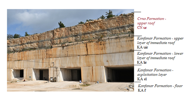
Figure 1: Deposit of “Kanfanar” Quarry
The basic structural characteristic of the dimension stone deposit of the "Kanfanar" Quarry is a massive rock containing large blocks separated by particular and very pronounced cracks of two discontinuity groups. The first group of discontinuities extends approximately in the northwest-southeast direction (135-315°) and the second in the northeast-southwest direction (65-245°). The discontinuities are mainly subvertical to vertical (85-90°) with very large persistence, more than 30 metres, and average spacings of 18-21 metres. The surface of the discontinuities is very rough and irregular, beyond all the usual measures of roughness (JRC, Jr), so that the rock blocks are interlocked in the exploitation layers and the immediate roof. In the case of such rock masses, due to their massiveness, it is not possible to obtain a realistic value of any classification system (RMR, Q, GSI), so other criteria must be applied to determine the strength and deformability of rock masses. In this way, the model of rock mass behaviour was assumed to be a continuous geotechnical model in terms of the observed mutual interlocking of the blocks on the discontinuity surfaces for which a new scale depended on correction method was developed. Namely, for obtaining the realistic in situ strength values of such a rock mass, a new coefficient of reduction was introduced on the basis of developed in situ flexural strength testing method (Hrženjak et al., 2013). By introducing a new coefficient of reduction, the strength parameters determined by laboratory tests can be corrected to obtain realistic values of the rock mass parameters. Based on the results of all the performed tests and applying appropriate corrections to the laboratory test results, the average values of the geomechanical properties of the rock masses were obtained, which are presented in Table 1 (Hrženjak et al., 2014).
Table 1: Rock mass properties
3. Numerical analysis
3.1. The SAP2000 computer programme
SAP2000 proved to be an interesting choice for modelling under conditions where a rock mass behaves as a continuum. In fact, it is an easily accessible programme with a wide range of applications, very well tested by its use in civil engineering, while its use in mining is not common.
SAP2000 is a modern computer programme designed for the calculation of stress and strain states of three-dimensional models according to the finite element method (FEM). From the three-dimensional representation of stress and strain states to the possibilities of applying various complex numerical analyses, which can be linear or nonlinear, assume an elastic or plastic form of stresses, use static or dynamic analysis, SAP2000 provides a simple and productive solution to the needs of structural analysis and design.
SAP2000 offers the possibility of phased modelling called “Stage construction analysis”, in which the analysis is performed sequentially for different model geometries or different loads. It was this type of analysis that was applied to gain insight into the stresses and strains before and after excavation (SAP2000 (Version 21)).
3.2. Input data
3.2.1. Geometry of the model
The default geometry of the model represents a quarter of the future excavation area, of which about a third is the excavation space and the rest is rock mass. Solid objects are used for the analysed model of the underground deposit of dimension stone. The model of the rock mass is divided into 5 different layers: the floor, the exploitation layer, the load-bearing lower layer of the immediate roof, the upper layer of the immediate roof and the layer of the upper roof, as shown in Figure 2.
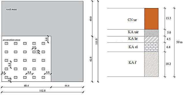
Figure 2: Geometry of the model: top plan at the quarter of the excavation area and layers of the rock mass.
3.2.2. Finite element mesh, assignment of loads and type of analysis
The possibility of phased modelling is used through “Stage construction analysis” in SAP2000. This enables a nonlinear static analysis in stages. Stage 1 represents the full rock mass model, stage 2 the post-exploitation model. Only the dead load of the layers is considered.
The model is divided into several smaller solid elements corresponding to the given geometry (see Figure 2), so that in the first stage it includes a full block with dimensions 112.8 m x 118.8 m, and in the second stage it includes an excavation according to Figure 2, as shown in Figure 3. The model contains 39,138 octagonal finite elements, and the total number of equilibrium equations is 121,176.
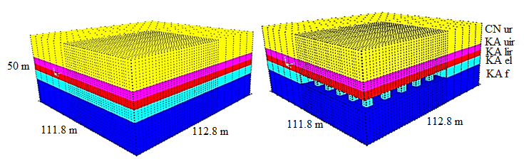
Figure 3: Finite element mesh of the model: a) Stage 1: the full block of the rock mass, b) Stage 2: the block after the exploitation.
3.2.3. Boundary conditions
At the bottom of the floor layer, the model is supported at all nodes in the x-, y- and z- directions, which prevents translational displacements and ensures the primary stability of the model. In the top view, over the entire height of the model, the boundary conditions are arranged according to Figure 4 due to symmetry, so that the model represents a quarter of the future exploitation field.
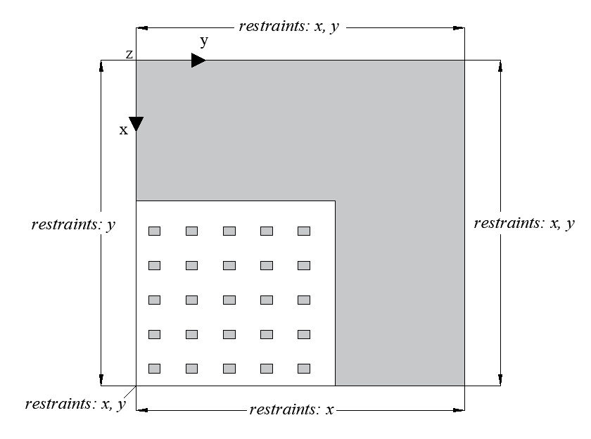
Figure 4: Floor plan view: boundary conditions
3.3. Results of numerical modelling
3.3.1. Stage 1: the full block model
For the complete block model (stage 1), the value of the primary vertical stresses in the central part of the exploitation layer is (see Figure 5), which corresponds to the analytical stress calculation. The value of primary horizontal stresses in the central part of the exploitation layer is .
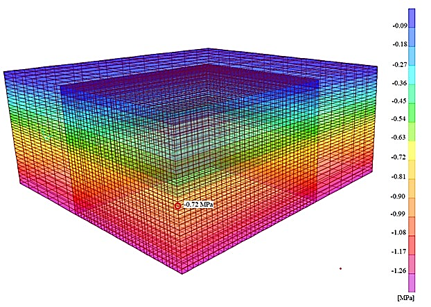
Figure 5: Stage 1: primary vertical stresses
The horizontal strains (x and y directions) are zero due to boundary conditions. The vertical strains (z-direction) are shown in Figure 6. The results are as expected: the values increase with depth, except for the layers of the immediate roof, since there the deformation modulus is much higher than in the upper roof layer (see Table 1).
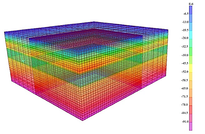
Figure 6: Stage 1: vertical strains
Figure 7 shows the vertical nodal displacements of the FEM mesh. The largest displacements are obtained at the top of the model and amount to 2.6 mm, whereas the displacements at the top of the exploitation layer (top of pillars) are 1.8 mm.
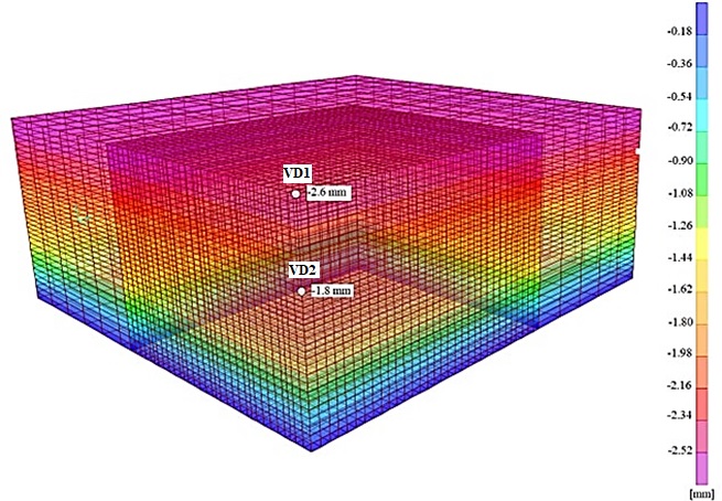
Figure 7: Stage 1: vertical displacements
3.3.2. Stage 2: post-exploitation model
For the post-exploitation model (stage 2), the highest values of vertical and horizontal stresses were obtained at the edges of pillars, (see Figure 8) and .
The vertical stress at the centre of the most heavily loaded pillar is (see Figure 8). The results of the vertical strains (z – direction) are in agreement with the previously determined stresses.
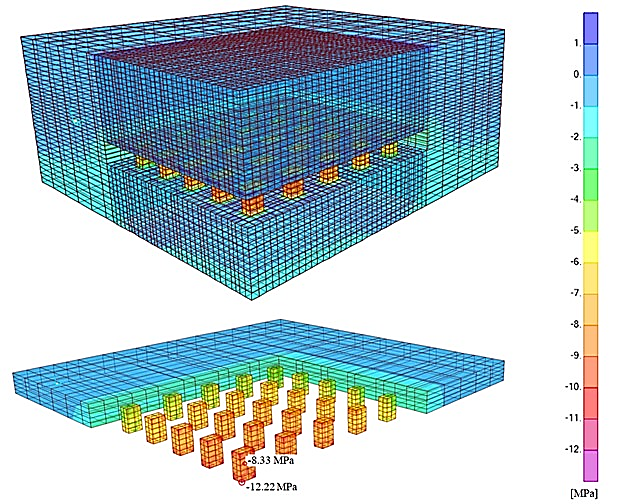
Figure 8: Stage 2: vertical stresses
Figure 9 shows the vertical nodal displacements of the FEM mesh. To obtain the relative vertical displacements caused by excavation, the displacements of the stage 1 model must be subtracted from the total displacements. The obtained maximum value at the top of the model is 10 mm (relative value: 10 - 2.6 = 7.4 mm), and the maximum value at the top of the pillar is 9.1 mm (relative value: 9.1 - 1.8 = 7.3 mm). The vertical displacements at the top of the model at about 40 m from the excavation field correspond to the displacements of the complete block model (VD1 in Figures 7 and 9; 2.6 mm), as do the vertical displacements at the level of the top of pillars at about 25 m from the excavation field (VD2 in Figures 7 and 9; 1.8 mm).
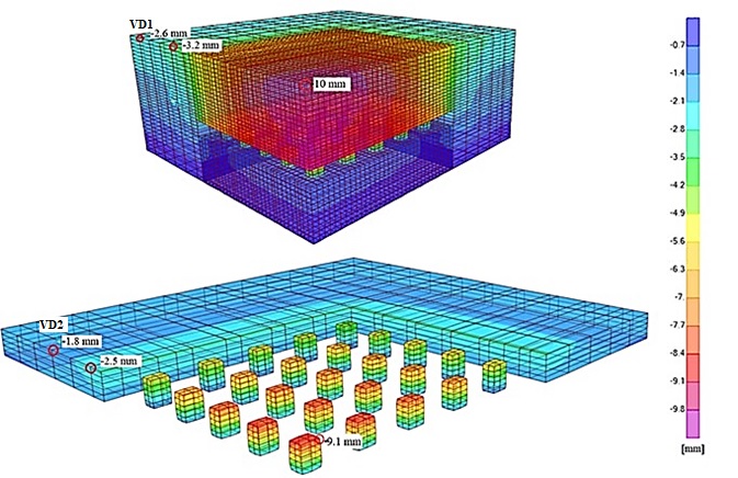
Figure 9: Stage 2: vertical displacements
4. Discussion
As far as controlling the results of numerical modelling is concerned, some revealing insights into the analysis of stresses can be obtained from simpler analytical solutions.
For a Poisson’s ratio of (see Table 1), the results for the full block model (section 3.3.1) confirm the relationship between the horizontal stresses and the vertical stresses according to the elasticity theory given in Equation 1 as follows:
(1)
For the post-exploitation model (stage 2), the strength factor of the point with the highest stresses, calculated as the ratio between the uniaxial compressive strength of the rock mass (see Table 1) and the maximum vertical stresses (Figure 8), is , which fulfils the stability condition, Equation 2:
(2)
The tributary area method, based on elementary concepts of static equilibrium, provides a simple method for determining the average state of axial stress in pillars, which can then be compared to the average strength of the rock mass representative of the particular pillar geometry (Brady and Brown, 2005). This is particularly true for a sufficiently large number of rooms and pillars when mining an ore body of uniform thickness and a lower thickness of overburden compared to the width of the mining area.
According to the theory of the tributary area method, the analytical expression for calculating the average value of the vertical stresses in the pillar is:
(3)
Where:
– primary vertical stresses in the rock mass (stage 1),
– the corresponding total area of the pillar of the roof deposits,
– cross-sectional area of the pillar.
According to Equation 3, the determined average value of vertical stresses in the pillar is , considering the primary stress state in the exploitation layers of 0.72 MPa (see Figure 5). This value is slightly higher than the value of 8.33 MPa in the centre of the most heavily loaded pillar obtained in the numerical analysis. However, it is appropriate to consider the implicit limitations of the tributary area method, which are mainly related to the neglect of the effects of the location of a pillar within an ore body or mining panel. The only appropriate solution can be obtained by the numerical analysis shown in Figure 8.
One of the main objectives of the numerical analysis was to determine the effect of underground excavation on the redistribution of stresses in the surrounding rock mass. Based on the solutions for vertical stresses (see Figure 8), a stress change of less than 10% was determined at a distance of 20 m from the underground excavation. The situation is, of course, quite similar for point displacements of the model (see Figure 9).
5. Conclusions
A numerical analysis of the part of the underground quarry of dimension stone with the designed maximum dimensions of the rooms was carried out to determine their stability and influence on the redistribution of stresses in the surrounding rock masses. The numerical analysis of the analysed model was performed with the SAP2000 software, which is intended for solving the stress and strain state of three-dimensional models applying the finite element method. SAP2000 is primarily used for the modelling of building constructions; however, in this paper the application of the programme in the field of mining was presented.
The obtained results confirmed the predicted behaviour of the rock mass. The highest concentrations of stresses and strains are found in the edge regions of the pillars, so their correct design is crucial. The analytically calculated average vertical stress in the pillar by the tributary area method is 9.06 MPa. Numerically, 8.33 MPa is obtained, and since this is the value in the pillar with the highest stresses, it can be confirmed that the results of the analytical calculation are on the safe side.
The strength factor of the point with the highest stresses was determined analytically and a value of 2.21 was obtained, which fulfils the stability condition.
6. References
Kruk, B., Dedić, Ž., Kruk, LJ., Peh, Z., Kovačević-Galović, E. and Gabrić, A.: Rudarsko-geološka studija potencijala i gospodarenja mineralnim sirovinama Istarske županije (Mining-geological study of potential and management of raw materials in the Istarska County). Hrvatski geološki institut, Zagreb (in Croatian)
Sari, M. (2022): Two- and three-dimensional stability analysis of underground storage caverns in soft rock (Cappadocia, Turkey) by finite element method. Journal of Mountain Science, 19 (4), 1182-1202.
Primjena računalnoga programa SAP2000 u modeliranju podzemnoga kamenoloma arhitektonsko-građevnoga kamena
Numerička analiza dijela podzemnoga kamenoloma arhitektonsko-građevnoga kamena s projektiranim maksimalnim dimenzijama podzemnih prostorija provedena je pomoću softvera SAP2000, temeljenoga na metodi konačnih elemenata. Glavni cilj analize bio je ispitati stanje stabilnosti i utjecaj na preraspodjelu naprezanja u okolnim stijenskim masama i time potvrditi primjenu teorije tributary area. Analitičkom primjenom teorije tributary area dokazano je zadovoljavajuće slaganje s numeričkim proračunom, pri čemu su rezultati dobiveni analitičkim proračunom na strani sigurnosti. Dobiveni rezultati potvrdili su predviđeno ponašanje stijenske mase, što potvrđuje primjenu SAP2000 softvera u području rudarstva, iako se radi o softveru s uobičajenom primjenom u području građevinarstva. Najveće koncentracije naprezanja i deformacija nalaze se u rubnim dijelovima stupova, stoga je njihovo pravilno projektiranje ključno. Određen je faktor sigurnosti točke s najvećim naprezanjima i dobivena je vrijednost od 2,21, čime je zadovoljen uvjet stabilnosti. Što se tiče utjecaja na okolno područje, na temelju dobivenih vertikalnih naprezanja na udaljenosti od 20 m od podzemnoga iskopa utvrđene su promjene naprezanja manje od 10 %.
Ključne riječi: SAP2000, numeričko modeliranje, metoda konačnih elemenata, podzemni kamenolom, arhitektonsko-građevni kamen
Authors’ contribution
Tanja Mališ (1) (PhD, Assistant Professor, Civil Engineering) performed the numerical analysis and consolidated the paper. Petar Hrženjak (2) (PhD, Associate Professor, Mining Engineering) performed the field research and laboratory tests, provided interpretations and presentation of the analysis results. Antonia Jaguljnjak Lazarević (3) (PhD, Associate Professor, Civil Engineering) provided the interpretation of numerical and analytical calculation. Mislav Mikulec (4) (mag. ing. min, Mining Engineering) performed numerical and analytical calculation for a smaller corresponding model through their master thesis (Mikulec, 2020).