
INTRODUCTION
Disaster management agencies use drones for carrying out special tasks on a daily basis. Their usefulness is undeniable. These aircraft have been one of the most important tools for assisting disaster management in recent years1. By using drones, not only can we shorten the time it takes to complete tasks, but we can also look at events from a perspective that we cannot obtain from ground level at all. With the help of well-known drone components – such as a camera or a thermal camera – we can transfer images/videos to the drone pilot. This information helps and speeds up decision-making on relief tasks. There may be cases in which the examined area is covered. This means the camera is no longer able to detect objects and people trapped under the covered area. During disasters and accidents, the primary goal is to save human life. Therefore, time is the primary factor. Our goal was to develop a drone component that, in addition to visual information, also supports rescue efforts with radiofrequency data.
DISASTER MANAGEMENT AND THE POSSIBILITIES OF USING A RADIO FREQUENCY DRONE COMPONENT
Drones currently used in disaster management perform the following tasks: • search and rescue tasks, • firefighting tasks, • law enforcement, prevention, and policing, • prevention of natural and industrial disasters. During search and rescue missions, disaster management agencies have to save lives in different terrain conditions. Drones with visual observation components can identify the human shape from a distance of up to tens of meters. With the help of a thermal camera, it can detect an organism with a different temperature than its surroundings even if it’s under a thinner cover. It transmits these videos in real-time to the search and rescue management team2. In all cases, the primary goal of firefighting tasks is to save and secure human life. The task of drones may be to locate a person/people trapped in a building or even in an enclosed area. But localizing the focal point of larger natural fires can also be done faster with these aircraft. Drones flying high see the target area from a different perspective, which is a huge help to firefighters. This added information allows them to do a faster and more accurate job, while their security is less at risk. In these cases, a regular camera image combined with a thermal image plays a prominent role3. In law enforcement, prevention, and policing, the tasks are multi-layered. The drones are suitable for mapping crime scenes, so the action of the law enforcement agencies can be planned more precisely. This can improve the outcome of an action and minimise the endangerment of civilian life. In addition to the traditional imaging component, infrared cameras also play an important role in crime prevention and policing. Nowadays, law enforcement agencies primarily use drones to control border violations and curfews. To prevent natural and industrial disasters, and to assist when they occur, drones are capable of performing tasks across multiple platforms. They can transmit a large amount of information to defence agencies and engineering teams that is invisible from the ground or difficult to access. This includes traditional imaging, but shots combined with a thermal imager provide even more information. For example, they can be used in case of a dam rupture to localise water breakthrough sites. In the event of an industrial disaster, a component capable of detecting hazardous gases integrated on the drone can predict hazardous locations for task performers.
INTEGRATION OF A RADIO FREQUENCY DRONE COMPONENT FOR DISASTER MANAGEMENT TASKS
Our current research focuses on how the information provided by existing imaging components can be combined with a drone-mounted radiofrequency reconnaissance component. We have found that the radio frequency scanner component we have developed can provide additional information to the ground team of disaster management organizations, primarily during search and rescue tasks and natural disasters4. The prepared drone component and the supporting software were named the SOS-SSID system. STRUCTURE OF THE SOS-SSID SYSTEM The new system has three components. During development, the drone-mounted radio frequency detection component was designed for an environment that includes the following elements: • terrestrial transmitter station (mobile device + sos application), • drone-mounted radiofrequency detection component + drone (hardware and software environment), • ground server system (drone navigation + sos application locator software environment). The structure of our system is shown in Figure 15,6.
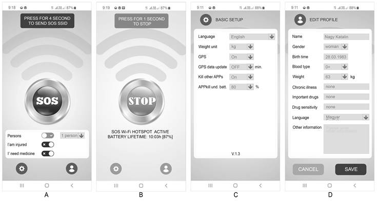
TERRESTRIAL TRANSMITTER STATION The ground transmitter station will be established by a software environment (SOS-SSID application) created for mobile devices. With this software, the person in trouble will be able to turn their device into a wireless network transmitter station, or – in other words – a hotspot. The mobile phone converted using the software can transmit information for assistance by radiofrequency for up to ten hours when charged. The windows of the program perform the following functions, which are shown in Figure 27. A) Main Screen – A large SOS button to initiate an emergency call. The function can only be activated by four seconds of continuous pressing, to eliminate accidental activation. Different kinds of instant information can be selected on the main screen using quick switches. Profile setting and basic setting options are also available as submenus. B) Emergency Call Active Status Screen – This page shows the emergency call application in active status. The following information is displayed here: The maximum expected operating time and battery charge, as well as the STOP button that interrupts the active service. In the active state, it is no longer possible to enter or modify basic data. This was necessary because the application had to generate a new SSID for each modification or new information. C) Basic Application Settings Screen – This interface allows the user to customize the application’s language, the unit of mass, the active status switch of the positioning system, the interval for regenerating the SSID due to changing coordinates, and settings for stopping other applications. D) Personal Profile Creation Screen – Provides basic information about the user. There are fill and select fields on the interface.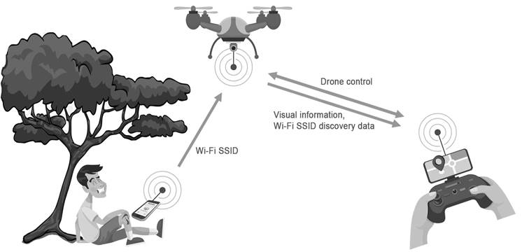
MEASUREMENTS WITH THE RADIO FREQUENCY DRONE COMPONENT
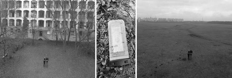
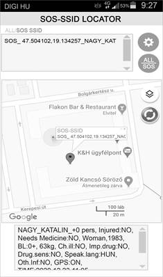
To obtain accurate results, we have done measurements on the efficiency of our development with different software and hardware pairings under different terrain conditions. Our tools used in the tests are: • ground mobile Wi-Fi hotspot – SOS-SSID transmitter (Vernee mobile), • drone and drone control (F550 drone), • Wi-Fi scanner application + drone-mounted data transmitter (Samsung A70), • evaluation applications (Wi-Fi heatmap scanner application, SOS-SSID decoder application on Samsung S10 and Huawei P20 mobile). We started our measurements with the SSID search. The radio system on the drone was set to scanner mode and the drone was given a pre-programmed flight path. After filtering the results obtained during the flight, we identified the exact location of the ground transmitter for SOS_XXXXXXXX. In the second step, we were able to localize the device using a Wi-Fi heat mapping application. This is a confirmatory test to verify that the device which provided the location data had sent it accurately. In the absence of accurate positioning data, the result of the second measurement leads to a target. FIRST SITE DENSELY POPULATED AREA Even before we started the measurements, we were aware that we would find several interfering Wi-Fi devices at this measurement site, which was confirmed by the scanning. At the time of the first measurement, 162 active Wi-Fi devices were listed, of which the SSID starting with SOS was easily identifiable. Figure 5 shows the result of a part of the measurement12,13.
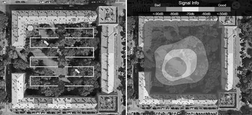
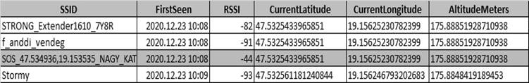
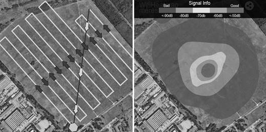
The coordinates recorded by the scanning application do not determine the exact location of the devices, but the drone’s location at detection. Therefore, a second, more accurate measurement based on Wi-Fi heat mapping is needed. It can determine the position of a specific SSID with an accuracy of a few meters14. The drone scanned around the coordinate of the SOS-SSID location identified in the first measurement. With this flight pattern and using the Wi-Fi Heat Mapping application, we got Figure 615. Second site – Field The method used for the first measurement was repeated at a second location, a field. From our experience, we knew that radio pollution would be lower at this location. Our assumption was confirmed, we were able to record a total of 4 SSIDs in the field, which also included our own SOS-SSIDs. Figure 7 shows our measurement result. Wi-Fi heat mapping was also performed at this location. Its result is shown in Figure 8.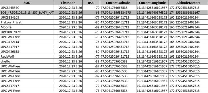
CONCLUSIONS
During the developments, we were able to create and successfully test an SOS-SSID radiofrequency system that may be suitable to be integrated into disaster management agencies’ systems. During our measurements, it was confirmed that the system we created works efficiently. All its components work in harmony with each other. With this system, the search time can be reduced and human life can be saved. The prepared article and the information contained in it demonstrated the operation of a prototype. Its integration into disaster management systems requires further development.