1. INTRODUCTION
With the advent of adaptive and cognitive antennas, the research on reconfigurable antennas is still on with new directions. Meta-surfaces are extensively studied in literature with various forms and configurations to design reconfigurable antennas. By the same way, parasitic patches are also used for the reconfigurable antennas. This antenna can steer the primary lobe in three distinct directions by reconfiguring a different frequency. By enabling the parasitic elements to behave like a reflector or director, PIN diode switches make pattern reconfiguration easier when adjusting their electrical length [1]. It consists of four L-shaped patches, two modified trapezoid-microstrip lines, a pair of vacant-quarter feeding loops, and four grounded inverted L-shaped strips. The antenna gain is enhanced by insertion of grounded inverted strips below the patches, enhancing its bandwidth and wider CP operation [2]. For a filtering antenna design, dipole antennas are used with an asymmetric parasitic element; utilizing it’s odd and even modes [3]. Metasurfaces are implemented for reflect array in [4] and performance enhancement of monopole antenna for few application-oriented implementations. A simple feeding network with 3×3 metasurface antenna designed in [5] has the capability to have LP, CP and also beam switching between 0⁰ and +30⁰. Square patch with diagonal slots on the radiator in [6], provides higher gain with the help of parasitic elements. Liquid metal-based polarizer is designed with two layers of micro fluidic channels in [7]. Circularly polarized antenna is proposed with the rectangular unit cells with truncated corners [8]. Conventional patch antenna is replaced with meta-surfaces as radiating elements in [9] gives low in band RCS. Here, operating frequency is reconfigured by loading the Varactor diodes. When the channels are empty it acts as the reflector and when the channels are filled with fluidic elements, it acts as the linear to circular polarization converter. To generate a wideband antenna consisting of one parasitic element placed between the dipole arms and two orthogonal bowties are used [10]. A broadband CP antenna is proposed with rotated parasitic patches in [11].
Non uniform meta-surfaces are embedded on the patch antenna gives wideband circular polarization in [12]. Corner truncated patch meta-surface is used to transform the linearly polarized wave into a circular polarized wave [13]. By rotating the meta-surface layer different polarizations are obtained. Dual band polarization reconfigurable antenna designed with double layer meta-surface [14], meta-surface embedded design for low RCS antenna in [15] used mechanical rotation of the substrate to aid the reconfigurable nature. Wideband CP antenna with high gain is obtained using mushroom cells [16]. Two-layerfabry-perot cavity antenna designed with parasitic element to exhibit beam steering in [17]. He substrate of this antenna is a bi-stable composite shell, which has two states for stretched and coiled-up [18]. Physical rotation of the meta-surfaces with the PIN diodes enabled the multi band operation from the antenna. A reconfigurable antenna array is made by using frequency selective surface (FSS) with PIN diodes in [19]. Mushroom type meta-surfaces exhibit penta-polarization in [20] and wide axial bandwidth in [21] are designed with two layers. Metamaterials are utilized to improve antenna gain and reduce side lobes, adjusted for the same frequency depending on research parameters such as size, bandwidth, and gain [22]. The antenna is circularly polarized, with four radiating slots fed by the dual coaxial probe [23]. In [24], a microstrip patch antenna printed on the ground plane loaded with dumbbell meta-atoms and loaded with stubs used to attain better performance and characteristics. A single truncated corner square patch, incorporating a corner cut square slot increases design flexibility by allowing wide bandwidth in circular polarization [25]. The antenna designed with reduced size and enhanced gain in [26, 27]. The metasurface based pattern reconfigurable antenna allows beam steering in the desired directions using four different slots placed from different positions [28].
The literature offers wide range of reconfigurable implementations with multiple layers or with complex geometries. The objective of the work is to design a compact polarization reconfigurable patch antenna with minimum number of diodes. A circular patch antenna is designed with four diodes which operate on 4.7 GHz. Section 2 talk about the design of parasitic element and the integration of antenna with parasitic elements. Section 3 discussed the performance of the antenna and the last section presented the conclusion.
2. DESIGN OF ANTENNA AND PARASITIC ELEMENTS
2.1. Design of parasitic elements
Set of two square shaped elements are infused like dumbbell shape to form the unit cell which is shown in Fig.1(a). The unit cell is characterized by the reflection coefficient (S11) to act as the parallel layer to the antenna element. The unit cell reflects all the incoming waves at 4.7 GHz with a bandwidth of 100 MHz. The selected geometry is an un-symmetric structure hence the TE and TM mode response has a small variation between S11 and S21 is presented in Fig.1(b). This unit cell is replicated on the radiating surface of the antenna to enhance the reflection from the antenna surface.

Fig.1. (a). Parasitic element with the dimensions are a=3.5 mm, b= 1.5 mm, W2= 10.5=L2

Fig.1.(b). Unit cell Characteristics (parasitic element)
2.2. Proposed Antenna Design

(a)

(b)
Fig.2. (a) Front view (L1=W1=60mm, w2=1.4mm, w3=1mm, g=20mm) (b) Back view
The antenna design starts with the circular patch with full ground plane. The dimensions of the antenna are 60 mm* 60 mm * 1.6 mm. Coaxial feed is used to excite the antenna and it resonates at 5 GHz. The location of the feed is chosen such a way that it induces the orthogonal modes. To enable the current rotation on either side, two arc shaped conductors are placed along the circular patch. Four diodes are placed on each corner of the arc to establish the contact between the patch and arc. The diodes are named as D1, D2, D3 and D4 which are marked on Fig. 2.
To improve the gain of the antenna, parasitic elements are arranged on the radiating plane with the inter element spacing (g) = 20 mm. This improved the gain of the antenna further. The S11 of the antenna undergoes a small shift due to the loading of parasitic elements.
2.3. WORKING PRINCIPLE OF THE ANTENNA
Surface current is observed on the radiator for different diode states. When D1 and D2 diodes are ON, the diagonally opposite arc radiators are connected with the disc radiator. Current rotation for different time incident is presented for Phi= 0⁰, 90⁰, 180⁰ and 270⁰ in Fig. 3 (a) & (b). The rotation is towards the right hand side which ensures the RHCP operation of the antenna. The surface current direction is marked on the circular patch for better understanding. When D3 and D4 diodes are ON, then the current rotation is towards the left hand side which ensures LHCP of the antenna.

(a)

(b)
Fig. 3.(a) RHCP Rotation (b) LHCP Rotation
3. PERFORMANCE ANALYSIS AND RESULTS DISCUSSION
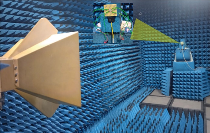
Prototype antenna is fabricated and tested for different metrics as reflection coefficient, radiation pattern and Polarization conversion ratio (PCR) values. Fabricated and chamber testing antenna is shown in Fig.4 (a) and (b). The diodes are biased and connected to the outer arc as shown in Fig. 4(a).

(a)
(b)
Fig.4. (a) Fabricated antenna (b) Measurement setup at Champer
3.1. REFLECTION COEFFICIENT
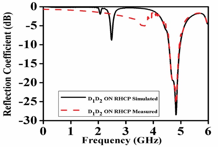
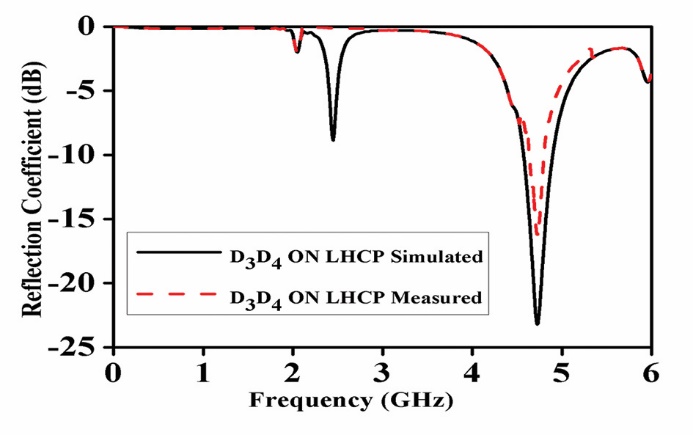
Reflection coefficient characteristics of the antenna is taken from simulated and measured in both operating modes. The results are presented in Fig. 5(a) and 5(b) respectively. The antenna resonates at 4.7 GHz with bandwidth ranging from 4.47 GHz to 4.89 GHz. The S11 for the antenna for RHCP and LHCP shows high correlation with the simulated results.
The simulated VSWR for both LHCP and RHCP are depicted in Fig. 6.
(a)
(b)
Fig. 5. Measured vs simulated S11 Characteristics
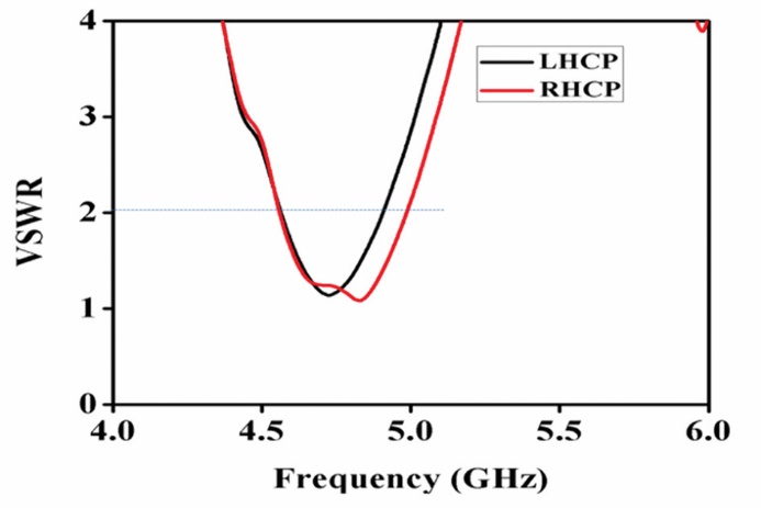
Fig. 6. Simulated VSWR Characteristics
3.2. POLARIZATION CONVERSION RATIO:
Polarization conversion ratio (PCR) is one of the metric to verify the suitability of polarization converters. The parasitic elements are verified for this metrics and are calculated from equation (1).
PCR= (1)
where |RYX| - magnitute of cross-correlation coeffiecient between Y and X.
|RXX|- magnitute of auto-correlation coeffiecient of X
The co and cross polarization results are obtained and the PCR is calculated and presented in Fig. 7. A very good conversion will have the value of 1 or nearer to that. The proposed parasitic elements are exhibiting the PCR of 0.9 in the working band. This is suitable for this antenna design and conveniently assisting for the circular polarizations from the antenna.
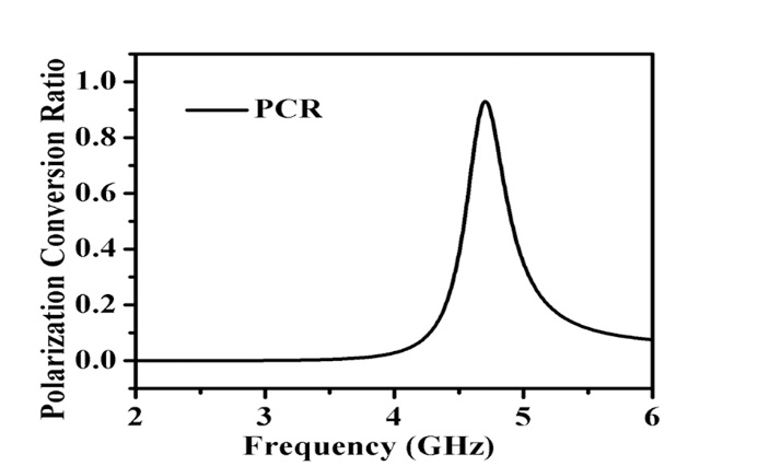
Fig. 7. Calculated (PCR)
3.3. Axial Ratio
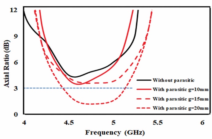
When parasitic elements are added to the antenna plane, they helped in improving the axial ratio through coupling Effects. Parasitic elements are strategically placed to create additional coupling between the elements of the antenna, which can help balance the electric field components. This balance is crucial for achieving good circular polarization. The parasitic elements can introduce phase shifts that compensate for any imbalances in the original antenna design. This helps in aligning the orthogonal field components more effectively, leading to a lower axial ratio.
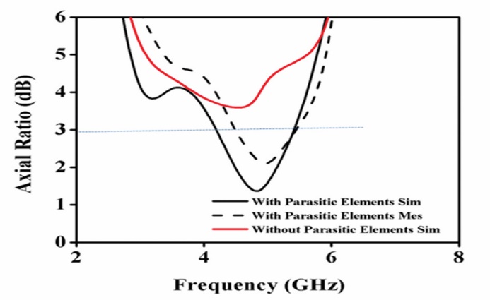
Axial ratio of the antenna is presented for different inter element spacing (g). The radiator without the parasitic element gives the axial ratio greater than 5 dB and the plot approached less than 3 dB for the value of g=20 mm. The parasitic elements are acting as polarization convertors and resulted in circular polarization with better axial ratio. It is clearly understood from Fig. 8 (a) and (b). that the 3-dB axial ratio of the antenna covers the impedance bandwidth of 320 MHz which is sufficient for sub 6 GHz applications. Measured gain and efficiency of the antenna is presented in Fig. 9. The gain of the antenna is improved by adding more number of parasitic elements with optimized inter element spacing. The maximum gain is observed to be 8.2 dBi compared with the references listed in Table 1. Form the table, the gain is maximum when the antenna size is larger and the proposed antenna is better than the references [6] and [11] in terms of size and gain. Radiation pattern of the antenna is measured in the working frequency and are stable irrespective of the biasing conditions which is shown in Fig. 10.
(a)
(b)
Fig. 8.(a) Variations of parasitic element with different gap (b) Measured Axial ratio of the antenna g=20 mm
Gain improvement of the antenna is due to the parasitic elements primarily because these elements can help direct and focus the radiation pattern more effectively. Parasitic elements act as the reflectors, guiding the electromagnetic waves in a more focused direction. This increased the directivity results in higher gain because most of the radiated power is concentrated in the desired direction. Properly designed parasitic elements can enhance the overall radiation efficiency by reducing losses due to impedance mismatches or unwanted radiation in non-preferred directions.
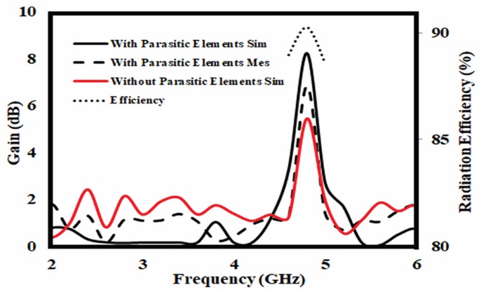
Fig. 9. Measured antenna gain and efficiency
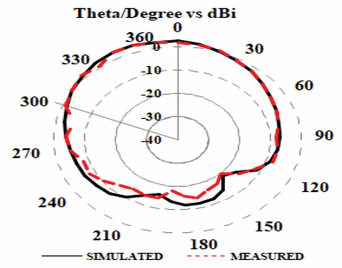
(a)
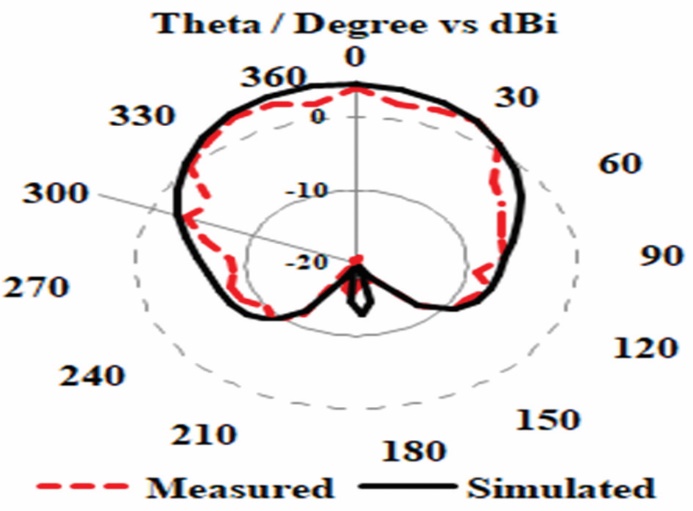
(b)
Fig.10. Radiation Pattern (a) 4.8 GHz (During LHCP) (b) 4.8 GHz (During RHCP)
Table 1. Comparison of Proposed Work with Existing Antenna from the Literature
4. Conclusion
The paper presented the parasitic elements loaded patch antenna for sub 6 GHz application. Polarization reconfigurable states of the antenna are verified with 4 PIN diodes and the antenna exhibits LHCP and RHCP rotation. The axial ratio bandwidth covered the C band between 4.5 GHz and 4.8 GHz. Working principle of the antenna is validated through current distribution and the measured results are in good agreement with the simulated results. The inclusion of parasitic elements improved the gain of the antenna significantly.
