
INTRODUCTION
Unmanned Aerial Vehicles (UAVs) or drones are nowadays utilised in a variety of commercial and defence-related processes. They have contributed substantially to broadening of diverse human activities through conducting them using, at least partially, the third dimension. One may argue that rapid enlargement of set of activities in which UAVs are used, whether as a crucial or as an auxiliary device, point to the fact that their potential in conducting different activities is still far from being developed.
UAVs mutually differ regarding their function1], henceforth regarding their different parameters such as are mass, flight endurance, maximal take-off weight, etc. along with different sets of sensors carried by UAVs.
One among the lines of development is a hybrid approach to the UAVs as mobile masts for ad hoc constructions in which they serve as sensor platforms or information transceiver hubs. In particular, a UAV is a heavier than air, carrying sensors and hovering on a fixed position during certain time interval. UAV’s electric motors are powered by electric current from a ground source. Thus the UAV is tethered, using suitable cable presumably for transfer of energy from ground source to the UAVs. Tethered lighter than air UAVs have been, since quite a long time ago, regularly utilised for long-term surveillances. Yet, they are rather sensitive to atmospheric conditions such as wind or wind gusts, what interferes destructively with the possibility of their use.
In this article we restrict analysis onto UAVs which are tethered, heavier than air, ground-powered, hovering sensor-carrying platforms. An eventual purpose of development of such a concept is the possibility to use such constructions in cases of emergency, when one needs rapid deployment of transceiver with sufficiently large range and quality of transmission, often in adverse weather conditions. Such approaches have already undergone some development[2-6].
A rather important parameter of such an approach is maximal height on which the UAV can hover for some rather long period of time. Since cable connecting the UAV with the ground power source has its own weight, in this article we analyse the concept of modular, self-supporting cable that powers a UAV on its top[7].
Section two contains the model. Section three contains the results, and section four the discussion of the results. Section five concludes the article and lists possible further development.
CONCEPTUAL MODEL
ELEMENTS AND ENVIRONMENT
We develop the concept of a powering cable, connecting energy source on the ground with a UAV hovering above it. The structure of the cable is modular. Each cable consists of a, in principle initially indeterminate, number of mutually identical modules. Along with the modules, cable is formed with two adapters, one connecting it to a ground power unit (GPU) and the other to a UAV.
Crucial requirement imposed on the module is that is self-supporting, in other words that it can hover in a still atmosphere. Additional requirements imposed onto it are: (i) every possible actuator that a module may carry utilises current of a same quality that is transported by the cable from the GPU to the UAV, and (ii) it makes possible transportation of sufficient electric energy. The last requirement is in fact naturally forwarded basic function of an
energetic cable, the module representing its sub-structure. In addition, for the presently adopted conceptual level, we impose the requirement that (iii) module is constructed out of certified, commercially available components.
Because of the last requirement, the dimensions of the wire, an electric conductor, and of the insulating shielding are standardised. Similarly, the materials of all these parts are of prescribed composition. As a consequence, the linear density of the complete cable, λ, is given in a form of discrete values. For the purpose of making the calculations more tractable, we broaden the list of parameters of available cables onto continuously variable parameters. Naturally, at the end we restrict the possible outcome of calculations onto the set of existing cables’ parameters.
Before proceeding, a note about the environment is appropriate. Eventually, such a modular cable is to be utilised in a variety of weather conditions, the more demanding the conditions the more important the rapid deployment of functional modular cable. In that sense one expect that there is a power reserve in the system that may be used to overcome effects of e.g. wind gusts. Along with that, one expects sufficient robustness of such a structure, making it rather suitable for manipulation. These requirements are partially fulfilled. First, robustness implies that every part of a cable is mechanically resistant to small shocks and moderate friction. That eventually reduces possible cables, since not all of them are predicted, and certified, for use in open space, subject to degrading and intense weather conditions. For the moment, we do not consider explicitly required power reserve, to be used for preserving the vertical, or close to vertical configuration in case of diverse weather conditions (wind gusts being a serious threat to such a geometry). Instead, we restrict our analysis at the conceptual level onto functioning of the cable in a still atmosphere, thus without significant wind and rainfall. It is reasonable to assume that, if a concept is logically consistent within some set of parameters, that there will be possible subset of these parametric values that would include also the aforementioned requirement for power reserve.
For further development of the concept, we assume that a module contains: four sets of mutually identical electric motor powered propellers; a frame; a processing unit; and two connectors aimed for establishing quick-release connection with other modules, or adapters found at both ends of the cable.
ELECTRIC CONDUCTORS
We extracted data from online sources of some of the commercially available electrical conductors aimed for use in open space. The data collected by no means form an exhaustive set, yet we did our best to form it as a representative set. However, if there had been a significant difference caused, its inclusion will change quantitatively some parameters but will not change the overall conclusions. From the collected data we formulated a constitutive relation between a linear density λ and a maximal direct current I that a conductor can carry for a long period of time:
λ(I) = kλ1I2 + kλ2I + Cλ. (1)
Values of coefficients were obtained after application of a least square method.
ELECTRIC MOTORS WITHIN A MODULE
For electric motors we choose Brushless Direct Current (BLDC) motors, following the representative type of existing small rotorcraft drones. From available data we formulated another constitutive relation, connecting mass of the motor m with the maximal power it can provide for a long period of time Pel:
m(Pel) = km Pel + Cm. (2)
Following the approach described in the subsection Electric conductors, we obtained the
coefficients in (2) for a representative, yet definitely not complete set of electric motors. In
particular we obtained km = 210–4 kgW–1 and Cm = 2,2610–2 kg, values that are used
throughout this article.
SELF-SUPPORTED MODULE
We assume that a module is capable of self-supporting it. Of course, that must be considered
carefully, since a module has to be connected to other modules forming a closed electrical
circuit. In that way we consider a stationary case, in which the lift generated by the propellers
connected to BLDC motors is in balance with the weight of the module. A general approach
is that the total lift must be somewhat larger than the total module weight, hence we start with
the following equation for stationary case:
TΣ = GΣ, (3)
with factor taking into account stated difference between the maximal total lift TΣ and total
weight GΣ, lift being equal to thrust of the propellers from all the motors, which is in the case
of quadrotor configuration of the propellers equal to
TΣ = 4T, (4)
with T being the lift provided by a single propeller. In (3) and (4) we did not explicitly took
into account aerodynamic drag of the module. Implicitly, it is incorporated in factor < 1.
Total weight equals
GΣ = λ(I)Lg + [4m(Pel) + m0], (5)
with L being the length of the module, and m0 mass of all other components – a frame for
motors, control unit and connectors – which are considered applicable with negligible
modifications for different L and I.
Electrical power Pel is in motors transformed into mechanical power Pmech. It is connected
with the thrust by the following relation for hovering rotor:
 , (6)
, (6)where A represents area of the circle described by the rotating propeller. Electrical and
mechanical power are related with the efficiency factor < 1:
Pmech = Pel. (7)
Finally, in case of direct current one has relation
Pel = UI, (8)
where voltage U is considered equal for each of the modules. Current I propagates through all
the modules. There are different was to electrically power all the control units and the motors.
Here we consider the case in which electrically all the control units are connected mutually
parallel. That is not the only case but, from the point of view of redundancy and thereby
introduced safety level, represents suitable starting point for analysis. The opposite case
would be that of the minimal redundancy, in which all control units are serially connected. In
case of parallel connections the current flowing through modules differs and is the largest in
the module connected to GPU. Let us consider that we have n (n = 1, 2, …) modules. In that
case current through the module connected to GPU equals nI and the total power becomes
Pel = UI. (9)
Expressions (1)-(8), when combined, bring about the following equation for the current through the module
C1I2 + C2I – C3I2/3 + C4 = 0. (10)
with the straightforward introduced coefficients
C1 = kλ1 L g n2, (11)
C2 = kλ2 L g n + 4km g U, (12)
C3 = 4 (2 A 2U2)1/3, (13)
C4 = Cλ L g + (4 Cm + m0) g, (14)
System (10)-(14) was solved numerically for a range of lengths L with constant voltage U = 12 V and other data for set 1 of conductors (Table 1). We consider only values of current that are real, not complex numbers.
RESULTS
Coefficients in the constitutive relation (1) for three sets of conductors are given in Table 1. Sets differ by the material of the conducting wire and insulating shield. Corresponding graph of the relation (1), for one of the sets of conductors, is shown in Figure 1. Precise values differ for other sets of conductors, but the quadratic form approximates the data well.
| Set of conductors | kλ1, kgm–1A–2 | kλ2, kgm–1A–1 | Cλ, kgm–1 |
|---|---|---|---|
| 1 | 0,00010 | 0,0030 | 0,0082 |
| 2 | 0,00002 | 0,0046 | 0,0634 |
| 3 | 0,00003 | 0,0058 | 0,0832 |
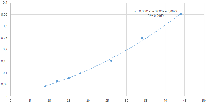
x=l, kg×m–1 y=I, A
Constitutive relation (2) is shown in Figure 2 for a representative set of motors. Precise values would differ for more exhaustive set of electric motors, but one may argue that linear relation would approximate data with a sufficient degree in the conceptual approach.
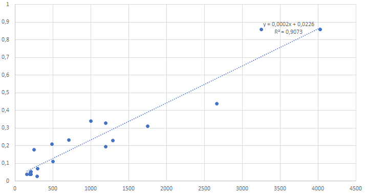
x=m, kg y=I, A
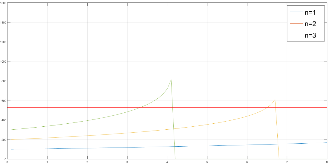
Current I through the conductors, obtained by numerically solving equation (10). The only physical solution is shown in Figures 3 and 4. In calculations value = 0,5 was used. Accompanied total power which should be provided by GPU is shown in Figure 5.
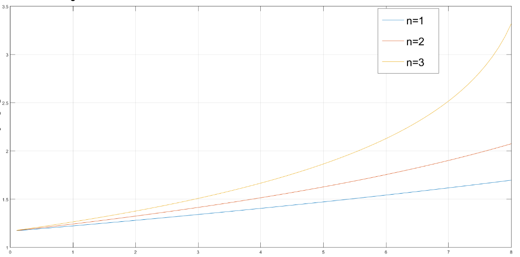
x=I, A y=L, m
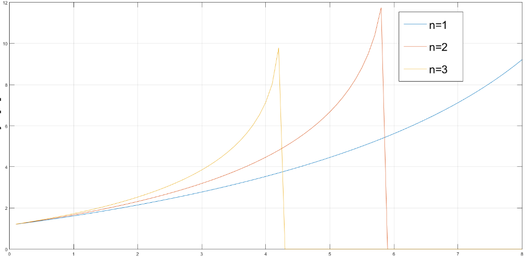
x=I, A y=L, m
x=I, A y=L, m
Total length of the cable is given in Table 2 for analysed combinations. All combinations belong to the same configuration in which modules are mutually identical and can carry total current flowing through a module.
| Set of conductors | Number of modules | ||
|---|---|---|---|
| 1 | 2 | 3 | |
| 1 | 14 m | 13 m | 12 m |
| 2 | 8 m | 9 m | 9 m |
| 3 | 6 m | 7 m | 6 m |
Concept of modular, self-supporting cable for powering the hovering unmanned aerial vehicle
DISCUSSION
Modular structure of the powering cable for making possible longer durations of hovering of drones is analysed. In prescribed configuration, on the conceptual level, modules are identical and carry uniquely defined current. Dependence of the total mass of the module on the allowed maximal current is well described with a quadratic polynomial. For a given class of electric motor, dependence of their mass onto generated power is sufficiently well described by a linear function. Naturally, owing to the numerical character of the solutions, more complex dependences were possible. Yet, having in mind that this is a conceptual level of approach and that underlying data do not form an exhaustive set of available data, the stated form of functions, as one may argue, is the optimal one.
A problem is transformed into an algebraic function that finally brings about the physically unique current flowing through the lowest module. That gives an insight into the general, nonlinear dependence of that current on a length of a module.
This is aligned with the fact that the longer a segment the larger its mass, bringing about a requirement of using a stronger electric motors, that additionally enlarge the module mass. For a fixed voltage large power implies larger current which, in a form of a feedback loop, requires larger cross-section of a module, eventually its larger mass. Self-consistently a unique relation between a current and a length of modules is obtained. It parametrically depend on a total number of segment having in mind the particular way of electrically connecting the modules. Foe any number of segments, there is a definite maximal length of a module because for larger lengths there is no physical current making possible self-sustained hovering of a module.
CONCLUSIONS AND PERSPECTIVES
Modular structure of the powering cable for making possible longer durations of hovering of drones is analysed. In prescribed configuration, on the conceptual level, modules are identical and carry uniquely defined current. Dependence of the total mass of the module on the allowed maximal current is well described with a quadratic polynomial. For a given class of electric motor, dependence of their mass onto generated power is sufficiently well described by a linear function. Naturally, owing to the numerical character of the solutions, more complex dependences were possible. Yet, having in mind that this is a conceptual level of approach and that underlying data do not form an exhaustive set of available data, the stated form of functions, as one may argue, is the optimal one.
A problem is transformed into an algebraic function that finally brings about the physically unique current flowing through the lowest module. That gives an insight into the general, nonlinear dependence of that current on a length of a module.
This is aligned with the fact that the longer a segment the larger its mass, bringing about a requirement of using a stronger electric motors, that additionally enlarge the module mass. For a fixed voltage large power implies larger current which, in a form of a feedback loop, requires larger cross-section of a module, eventually its larger mass. Self-consistently a unique relation between a current and a length of modules is obtained. It parametrically depend on a total number of segment having in mind the particular way of electrically connecting the modules. Foe any number of segments, there is a definite maximal length of a module because for larger lengths there is no physical current making possible self-sustained hovering of a module.