
INTRODUCTION
Soft robotics is a growing field that focus on constructing robots out of soft materials. The term soft refers to materials that share similar stiffness as materials found in natural organisms. While traditional robots are made of hard materials such as metals, with Young’s modulus in a range of 109-1012 Pa, biological materials such as skin and muscles have Young’s modulus of much lower magnitude, typically around 104-109 Pa[1]. Engineering materials such as silicones, rubber, hydrogels etc. fit well into this range which makes them considered as soft materials and capable for use in soft robotics. Today, additive technologies are advantageously used to manufacture very complex designs with unintuitive mechanical properties[2,3].
Using materials with low stiffness means that they will be subjected to large strains during use. In case of soft robots, this property is desirable because it enables different applications such as grasping[4,5], locomotion[6-9], and sensing[10,12]. Unlike conventional robots which are functional only in highly defined environment, soft robots provide much more flexibility when it comes to grasping objects. They conform to the shape, excluding possibility of concentrated pressure that can damage object which makes them safe for grasping soft and sensitive objects as well as objects which shape is originally unknown. Large deformations and ability to adapt brings to conclusion that soft robots can achieve theoretically infinite degrees of freedom with only one input[13].
Compatibility in stiffness between soft and natural materials makes them able to resemble movements of natural organisms. This property is highly exploited in the field of biomimetics where soft robots proved successful to mimic locomotion of various animals, e.g.: fish[6], worm[7], snake[8], octopus[9], artificial muscles[14] etc. These extraordinary movements require new sensors that can follow the large deformations of a soft body. A breakthrough in this field is already made with so called soft sensors[10,12]. Absence of rigid component makes soft robots inherently safe for interactions with humans. In the area of medical robotics, soft robots are used for wearable devices that improve rehabilitation process for patients with musculoskeletal diseases such as arthritis, cerebral palsy, Parkinson’s disease, and stroke[15,16]. Continuum kinematics and ability to navigate through narrow spaces without damaging the surrounding environment makes them ideal candidates for minimally invasive surgery, particularly in the field of endoscopy[17]. Appropriate control algorithms for efficient path planning of such robots, when sharing environment with other moveable objects, should be developed and tested, similarly to the classical robotic field[18-20]. Additionally, there is a lack of formal modelling of in soft robotic literature, although some important findings have been made recently[21--25].
Soft robots can be actuated in many different ways: using cables or shape memory
alloys[26,27], electrically using electroactive polymers[28] or pressure driven, using pneumatics[12, 29, 30], or hydraulics[31]. Although there are many different types within family of soft pneumatic actuators[32], we focus on Bellows-type[5]of soft pneumatic networks. The structure of these actuators is made out of connected chambers which, once subjected to pressure, result in bending of entire actuator. Small chambers require less volume and less pressure for actuation, making them fast and efficient[33]. When compared to tube shaped actuators, Bellows type experience lower strain which suits them better for less flexible materials such as TPU. Since the whole structure is modular, by selective actuating of single cells, specific motions can be achieved. Bellow type of actuators consist of only one part which makes them suitable for 3D printing or casting.
Despite large popularity of research in the field of soft pneumatic actuators, very few of them are occupied with strictly formal modelling. Unlike conventional robots whose links are of correct form, structure of soft robots is often too complex to be expressed by mathematical equations, so different approach must be chosen. Additional problems arise because of highly nonlinear material behaviour and large strains. In this article we present a procedure for improving structure of Bellows-type of soft pneumatic actuators, using finite element analysis (FEA).
MATERIALS AND MODELLING
Soft pneumatic networks are usually made out of two materials: silicone rubber and thermoplastic polyurethane (TPU). The first one shows more flexibility and is more often used as material for pneumatic actuators but can be fabricated only by casting. Since we plan to use direct 3D printing process, we will rely on TPU. This material belongs to the class of thermoplastic elastomers that shares both thermoplastic and elastomeric properties. Combination of properties gives them ability to be stretched to moderate elongations and at the same time to be processed by melting. From many available TPU filaments, we have chosen to use NinjaFlex because it is most widely known and commercially available. As it can be seen from Table 1, it offers great flexibility and tensile strength.[34].
| Mehanical Property | Value | ||
|---|---|---|---|
| Yield strength | 4MPa | ||
| Youngs modulus | 12MPa | ||
| Tensile strength, ultimate | 26MPa | ||
| Elongation at break | 660 % |
We begin improving process with designing initial structure.
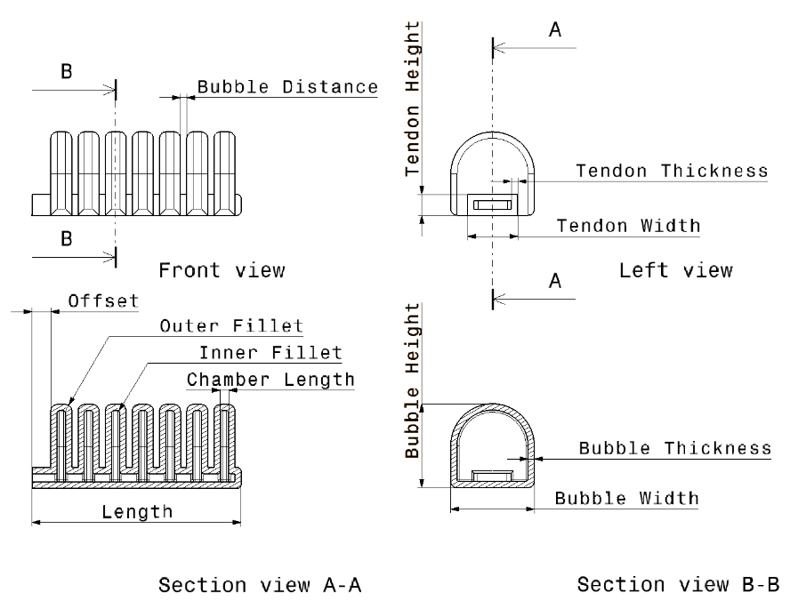
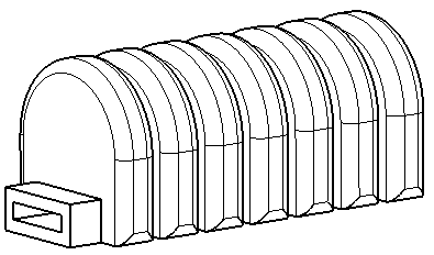
Three requirements have been chosen for design of actuator: (1) it should withstand maximum pressure of 1 bar, (2) maximum stress should not be higher than yield strength of material which is 4MPa, (3) cross section should not exceed 20x20 mm. This last requirement is added so that dimension of actuator approximately fit dimensions of human finger. The 3D model is made in CATIA using parametric design which allows instantaneous redefinition of complete structure with change of a single parameter. Initial design is displayed in Figure 1. Entire structure can be described with a total of 12 parameters whose initial value are given in Table 2. Length and Offset are not meant to be changed while other 10 parameters will be, one by one, subjected to FEM analysis.
For any kind of structural analysis, it is necessary to have an accurate material model. In the most basic form, it implies knowing relations between stress and strain. Most common engineering materials such as metals show linear elasticity below yield strength which makes them easy to model according to Hooke’s law, using only Young modulus as a parameter.
On the other hand, rubberlike materials, such as TPU belong to the class of hyperelastic materials which exhibit nonlinear stress-strain behaviour even in the zone below yield strength. In this case Youngs modulus can be relevant only for near-zero values of stress and strain and since we aim to achieve large deformations, it cannot apply. Furthermore, there are numerous factors that affect properties of polymers, such as molecular weight, processing, etc. meaning that same material can have differing properties within different manufacturers. For this reasons, only reliable way to determine needed relations between stress and strain is to obtain them as a result of tensile testing for exact material. Most filament manufacturers do not offer this data and situation is no different for NinjaFlex. Luckily, a work of T. Reppel and K. Weinberg[35] is all about determining stress-strain relations of a 3D printed NinjaFlex so we will use data from their experiments.
Defining a hyperelastic material in Abaqus can be done in two ways. First, by entering table data of tensile tests. Up to 4 different test data can be entered: uniaxial, biaxial, planar and volumetric. For an incompressible isotropic material, uniaxial test data is often enough to get decent results, although Abaqus documentation recommends combining multiple tests for better accuracy[36]. Secondly, by setting a strain energy density function with necessary parameters. User can select between several different formulations but we focus on Ogden model since it generates the best fit[35, 37].
Ogden model is a function that describes nonlinear stress-strain behaviour of rubberlike solids. Essentially it is a compact way to approximate results obtained from uniaxial test, using only couple of parameters that define material. Since we do not have tensile test data at disposal, for our simulation, we will use parameters that T. Reppel and K. Weinberg calculated in[35]. Nevertheless, for completeness of this article, procedure of acquiring these parameters is described in following section.
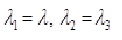
Ogden’s formulation express strain energy density W in terms of principal stretches λj; j=1,2,3.
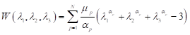
where W represents strain energy density, N represents strain energy order while μP and αp are material parameters. Next step is to make reasonable assumptions that will simplify (1). Rubberlike materials experience very little compressibility compared to their shear flexibility so in applications where material is not highly confined to small spaces, assumption of incompressibility gives satisfactory results[36]. For incompressible materials, constraint (2) must be satisfied.
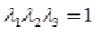
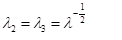
Although rubberlike materials generally show isotropic properties, because of our production method, 3D printing, one has to be careful. As it is shown in[37], using diagonal infill with one line of shell brings us close to isotropic properties. Under assumption of isotropic material and uniaxial tensile stress, principal stretches can be expressed as:
From (2) and (3) we get relation between stretches:
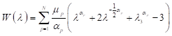
Inserting (4) into (1) gives us Ogden model for incompressible isotropic material under uniaxial stress:
Finally, partial derivation of stain energy density with respect to stretch give us stress strain relation for uniaxial case[26]:
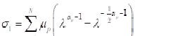
By combining test data, (6) and numerical algorithms for curve fitting we can derive constants μ_P and α_p of hyperelastic material. Usual practice is to start curve fitting with strain energy order N = 1 and gradually rise it if results are not satisfactory. Hill’s criterion should apply to ensure material stability [38]:
Ogden model in Abaqus is defined slightly different than (1) so after calculating μ_P and α_p, adjustment needs to be made.
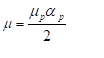
In the simulations presented in this article, we used second order Ogden with parameters as given in Table 3. Parameters D1 and D2 are left 0 for incompressible materials[36]. Resulting stress-strain curve is shown on Figure 2.
Due to high strains, “geometrically nonlinear analyses” option must be selected in Abaqus. Meshing is performed using quadratic tetrahedral hybrid elements (C3D10H). Hybrid formulation is recommended for incompressible or close to incompressible materials. Seed size is set to 1mm and lowered if needed, ensuring that there is always two layers of elements along structure walls. Above setting typically generated around 50 000 elements. Every model was subjected to pressure of 1 bar.
RESULTS AND CONCLUSIONS
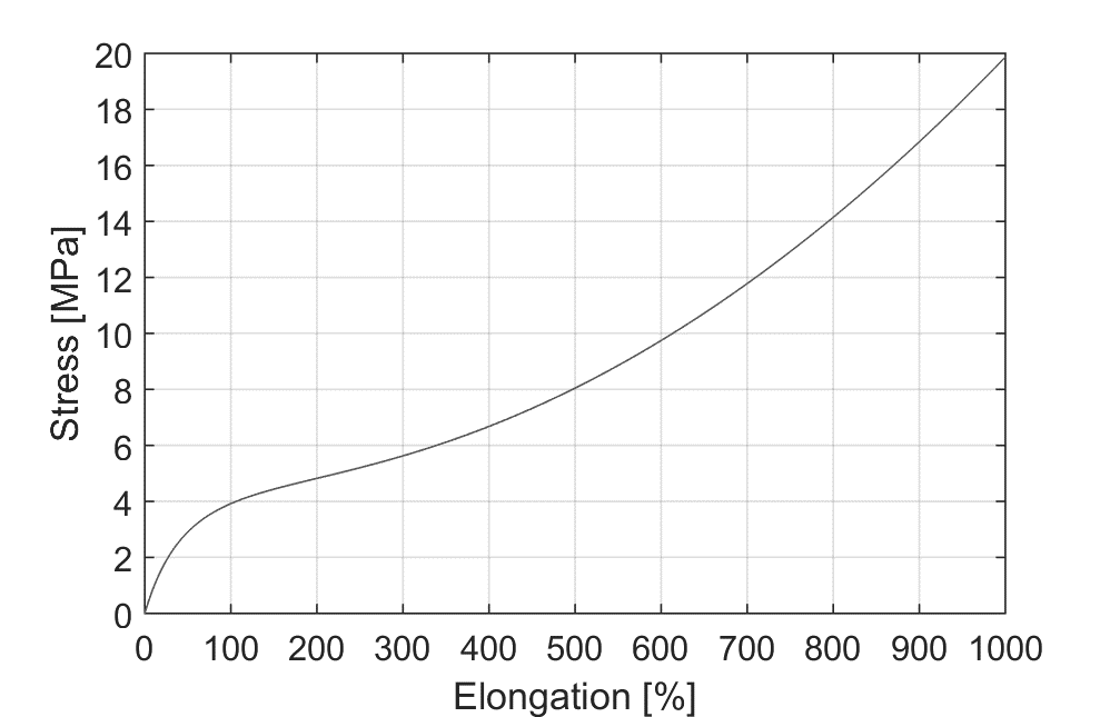
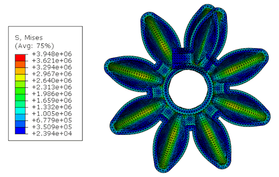
With respect of material and above-mentioned settings, FEM analysis was performed 11 times. First, to get result for Prototype 1 which serves as a reference, and then for every other parameter separately. Changing only one parameter at the time allows us to observe its impact on the structure. Two features were measured – maximum stress in the volume, and bending angle of the whole structure. Increase in bending angle is considered positive change while increase of maximum stress is considered negative. These values for the Prototype 1 are: Bending angle: 220º, and Maximum stress is 4.547 MPa., Results of the initial simulation and parametric study are illustrated on Figure 3.
From Table 4 we can observe that some parameters have strong influence while others are less significant. Usually positive impact on one feature follows negative impact on other but there are also features that have both positive and both negative impacts.
More often is that one parameter has bigger impact (positive or negative) on one feature and less on the other. Idea is to always choose properties that have more pronounced positive impact.
From what we learned in Table 4, a new set of parameters is defined (Table 2, Column 3 – Prototype 2. Reducing Bubble Width and Bubble Height proved to have a strong negative effect on bending angle while decrease in stress less notable. Increasing these dimensions could make an opposite effect but because of our requirement on the cross section, these dimensions remained the same. Reducing Bubble Thickness has major impact on increase of bending angle so this value is reduced to 1,2 mm which is a theoretical minimum bounded by the nozzle
diameter, of the 3D printer used (Prusa I3). Since we plan to use 3D printer, we have to think about layers when deciding about the thickness property. According to [39], thickness should be in multiples of the nozzle size and there should be at least three layers to ensure airtightness. Since we plan to use 0,4 mm nozzle, we will stick to values of 1,2 mm and 1,6 mm when choosing thickness property. Dimensions that are longitudinal, Chamber Length and Bubble Distance do not have strong effects so they are decreased in order to fit another two bubbles on the structure. Higher density of bubbles will increase the bending angle. Decreasing Tendon Width has the most positive impact of all properties – at the same time it increases bending angle and decreases maximum stress. Since we decreased it to 6 mm, we increased Tendon Height, whose impact is insignificant, to ensure good air flow. Reducing Tendon Thickness proved to increase stress in material so to achieve an opposite effect we increased this value to 1,6 mm. Increase of Inner Fillet has the strongest impact on reducing stress so it is set to the maximum value – half of the chamber length.
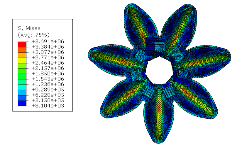
After FEM analysis was run for Prototype 2, we can observe large increase of bending angle. Overlap is allowed to measure this increase. Bending angle increased almost double: +90,9 % while stress is lowered for –13,2 %.
By observing a detail view, Figure 4, we noticed that maximum stress values are always concentrated on the bottom wall, underneath the chamber. This is also a point where largest
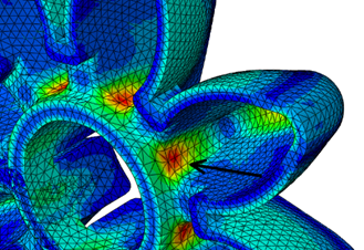
strains are expected and consequently a point where structure will break most likely. By removing material from this point, structure is able to bend more freely resulting in lower strains.
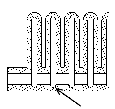
As it can be seen on Figure 5, making an indent on the place of maximum stress improved our structure even more. When compared to Prototype 1, bending angle is increased by +113,6 % while stress is lowered by –18,8 %.
Final confirmation of the approach presented in the study will be upon conduction a thorough experimental validation for the specimens proposed. In this article, the authors have tried to give important aspects to consider when trying to improve the structure of a soft actuator based on the Bellows structure. Some of the correlations between different parameters and their impact to the actuators’ behaviour are revealed. It would be interesting to formally describe the dependency between the parameters and the response of the actuator, in order to reveal the nature of different parameters. This requires additional experimental validation and will be included in our future research. and These actuators are becoming largely present in mainstream robotics and will be even more in the future, so insight in their structural properties is essential.